Graphically Manage Shared Interfaces, Data Types, and Constants
The Architectural Data section of a Simulink® data dictionary enables interfaces, data types, constants, and AUTOSAR-specific data to be authored, managed, and shared between AUTOSAR components and compositions modeled in Simulink. The Architectural Data section provides scalability for system-level and multicomponent designs by containing these shared elements in a central location.
You can configure architectural data and apply your changes to a model using this basic workflow:
Create a data dictionary.
Design interface, data types, and constants with the Architectural Data Editor.
Link the data dictionary containing architectural data to a Simulink or architecture model.
Apply architectural data to a model in the Simulink environment.
Create Simulink Data Dictionary and Open Architectural Data Section for Editing
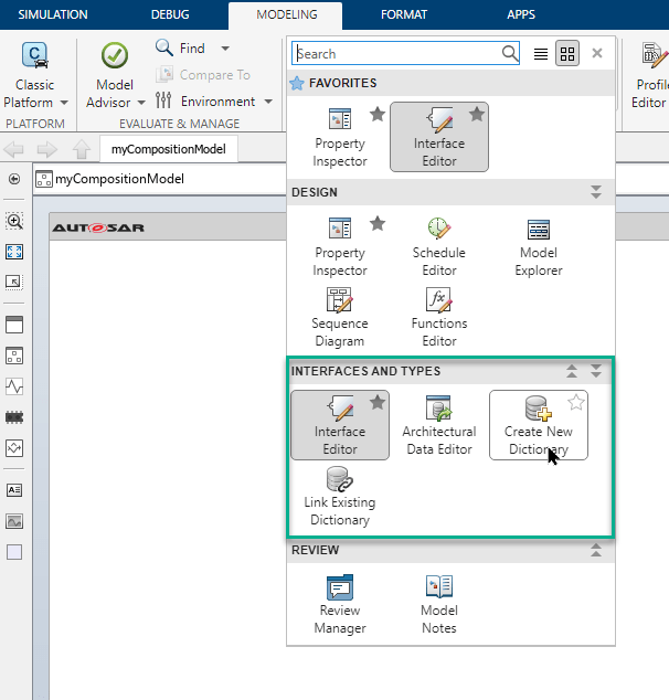
To create a data dictionary from the AUTOSAR architecture model toolstrip, on the Modeling tab, open the Design gallery, and select Create New Dictionary from the Interfaces and Types section.
Design Data Types, Interfaces, and Constants Using Architectural Data Editor
Once you create your data dictionary, you can add and edit architectural data using the Architectural Data Editor. This tool allows you to author elements shared outside of the context of a particular component or composition and allow multiple team members to define and manage these elements.
Open Architectural Data Editor
To open the editor from an AUTOSAR architecture model:
In the Simulink editor of an AUTOSAR architecture model, on the Modeling tab, open the Design gallery and select Architectural Data Editor.
To open the editor from outside the context of a model, use one of these methods:
In the MATLAB® Current Folder browser, navigate to and double-click the
.slddfile to open Model Explorer. Expand the data dictionary file and select Architectural Data, then click Open Architectural Data Editor from the Dialog pane.Use the
showfunction on an Architectural Data object created usingSimulink.dictionary.archdata.createorSimulink.dictionary.archdata.open.Enter
archdataeditorat the MATLAB command line.
Add and Configure Data Using Architectural Data Editor
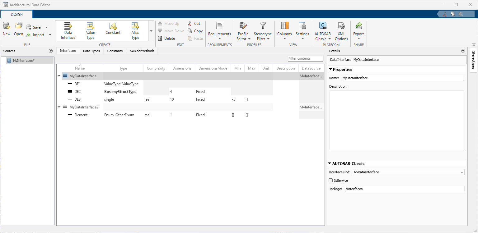
With the Architectural Data Editor, you can create, configure, and manage architectural data.
Create — On the toolstrip, in the Create section, add data type definitions, interfaces, and constants. Data types, interfaces, and constants each have a dedicated tab for data management.
Configure — In the right panel, use the Details pane to configure your data. The Details pane can also display platform-specific properties.
For example, when you set the deployment platform to AUTOSAR Classic, the Details pane displays AUTOSAR interface communication properties such as InterfaceKind, IsService, and Package.
Manage — You can filter, sort, and search data on the Interfaces, Data Types, and Constants tabs.
In addition to the Interfaces, Data Types, and Constants tabs, the Architectural Data Editor displays platform-specific software address method data for the AUTOSAR Classic Platform in the SwAddrMethods tab.
Link Data Dictionary to Model
To link an existing data dictionary from the AUTOSAR architecture model toolstrip, on the Modeling tab, open the Design gallery and select Link Existing Dictionary from the Interfaces and Types section. When you create a component model from an AUTOSAR architecture model, Simulink automatically links it to the data dictionary.
Use Interface Editor to Apply Interfaces to AUTOSAR Model
Alternatively, you can apply the interfaces to your AUTOSAR model by using the Interface Editor or Property Inspector. In the AUTOSAR model toolstrip, on the Modeling tab, open the Design gallery and select Interface Editor. The editor opens as a pane in the current Simulink editor window.

The primary focus of this model-centric editor is applying interfaces to ports. It displays the available interfaces in the linked data dictionary. See Interface Editor (System Composer) for more information.
By using the Interfaces tab you can:
Assign an interface to a selected port on the canvas by right-clicking on the interface.
Trace between ports and interfaces.
Focus on a particular interface by using the Port Interface View.
View and configure a selected interface by using the Property Inspector.
Limitations
Some limitations for AUTOSAR mapped data dictionaries include:
Data dictionary reference hierarchies are not supported for data dictionaries mapped to the AUTOSAR Classic Platform.
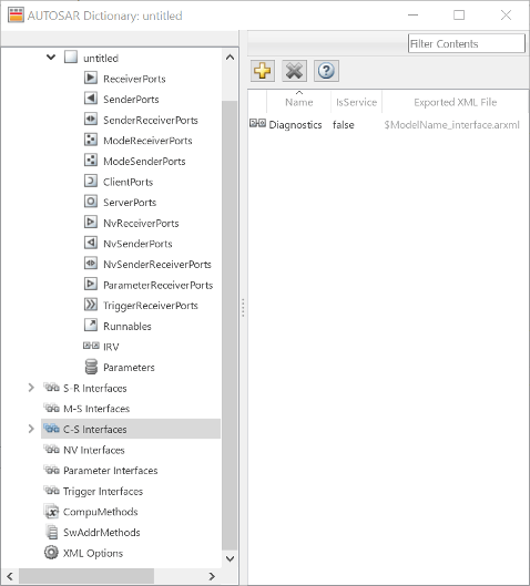
The Interface Editor (System Composer) can only view and edit data interfaces. To author and view other kinds of interfaces for AUTOSAR workflows, such as client/server, parameter, and trigger interfaces, use the AUTOSAR component dictionary.
The data dictionary does not support the import of AUTOSAR information from an ARXML file.
See Also
Architectural Data Editor | Property Inspector | Simulink.dictionary.ArchitecturalData | autosar.dictionary.ARClassicPlatformMapping | exportDictionary | getPlatformProperties | getPlatformProperty | setPlatformProperty | Simulink.dictionary.archdata.create | Simulink.dictionary.archdata.open
Related Topics
- Programmatically Manage Shared Interfaces, Data Types, and Constants of Architecture Models
- Create AUTOSAR Architecture Models
- Add and Connect AUTOSAR Classic Components and Compositions
- Define AUTOSAR Component Behavior by Creating or Linking Models
- Generate and Package AUTOSAR Composition XML Descriptions and Component Code
- Author AUTOSAR Compositions and Components in Architecture Model
You can also select a web site from the following list:
Americas
- América Latina (Español)
- Canada (English)
- United States (English)
Europe
- Belgium (English)
- Denmark (English)
- Deutschland (Deutsch)
- España (Español)
- Finland (English)
- France (Français)
- Ireland (English)
- Italia (Italiano)
- Luxembourg (English)
- Netherlands (English)
- Norway (English)
- Österreich (Deutsch)
- Portugal (English)
- Sweden (English)
- Switzerland
- United Kingdom (English)