Define Custom Board and Reference Design for AMD Kria KV260 Vision AI Starter Kit
This example shows how to define and register the custom board and custom reference design for AMD® Kria® KV260 Vision AI Starter Kit using HDL Coder™. You create the reference design to control the LEDs connected externally through the PMOD connector. You can follow the steps in this example to define and register the custom board and reference design for other Zynq® Ultrascale+ MPSoC platforms.
Requirements
To run this example, you need:
The Xilinx® Vivado® Design suite. For a list of supported versions, see HDL Language Support and Supported Third-Party Tools and Hardware
AMD Kria KV260 Vision AI Starter Kit.
HDL Coder Support Package for AMD FPGA and SoC Devices.
Create and Export Custom Reference Design Using Xilinx Vivado
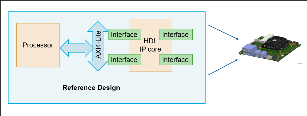
A reference design is an example project that demonstrates the connection between different parts of the system. You can use HDL Coder IP Core generation workflow, to create a custom IP core that fits into this reference design. Then you can use this combined design to create Vivado project, generated bitstream and program the target using HDL Coder. The diagram below shows how the reference design, the IP core, and the board are related.
To create and export a reference design by using Xilinx Vivado IP integrator, please follow these steps.
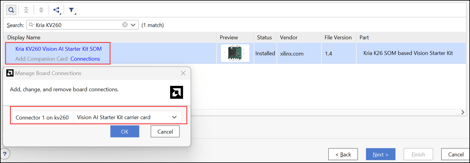
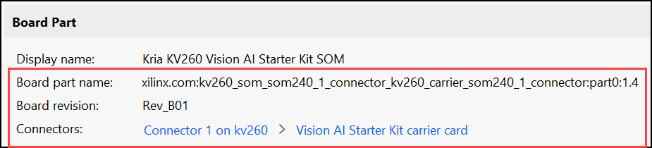
1. Open Xilinx Vivado and create an RTL project by adding the necessary source files and the constraint files. In the board selection step, click the Boards tab and select AMD Kria KV260 Vision AI Starter Kit SOM as the target device. If you want to add the companion card and manage the connections to the SOM, click the connections option as shown below.
2. To create a block design in Vivado, click the Create Block Design option in the IP Integrator drop-down list. If you want your programming logic (PL) to communicate with the processing system (PS), add the Zynq UltraScale+ MPSoC Processing System IP block to the block design. After adding the PS IP block, run the block automation.
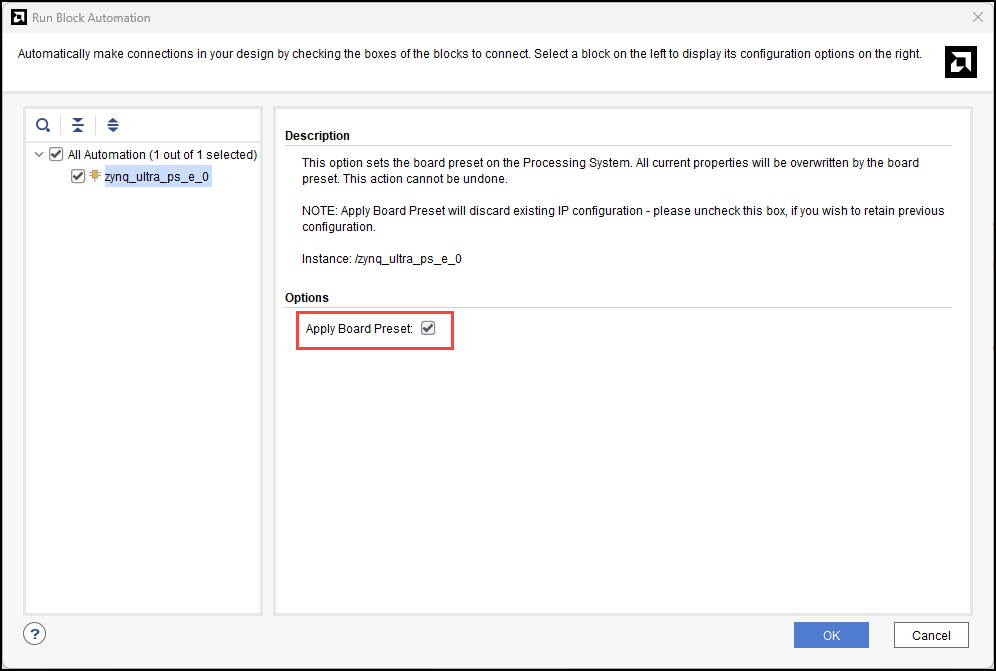
3. To set the board preset on the PS, select the Apply Board Preset check box. After applying the board preset, the block design marks the MIO peripherals according to the board definition.
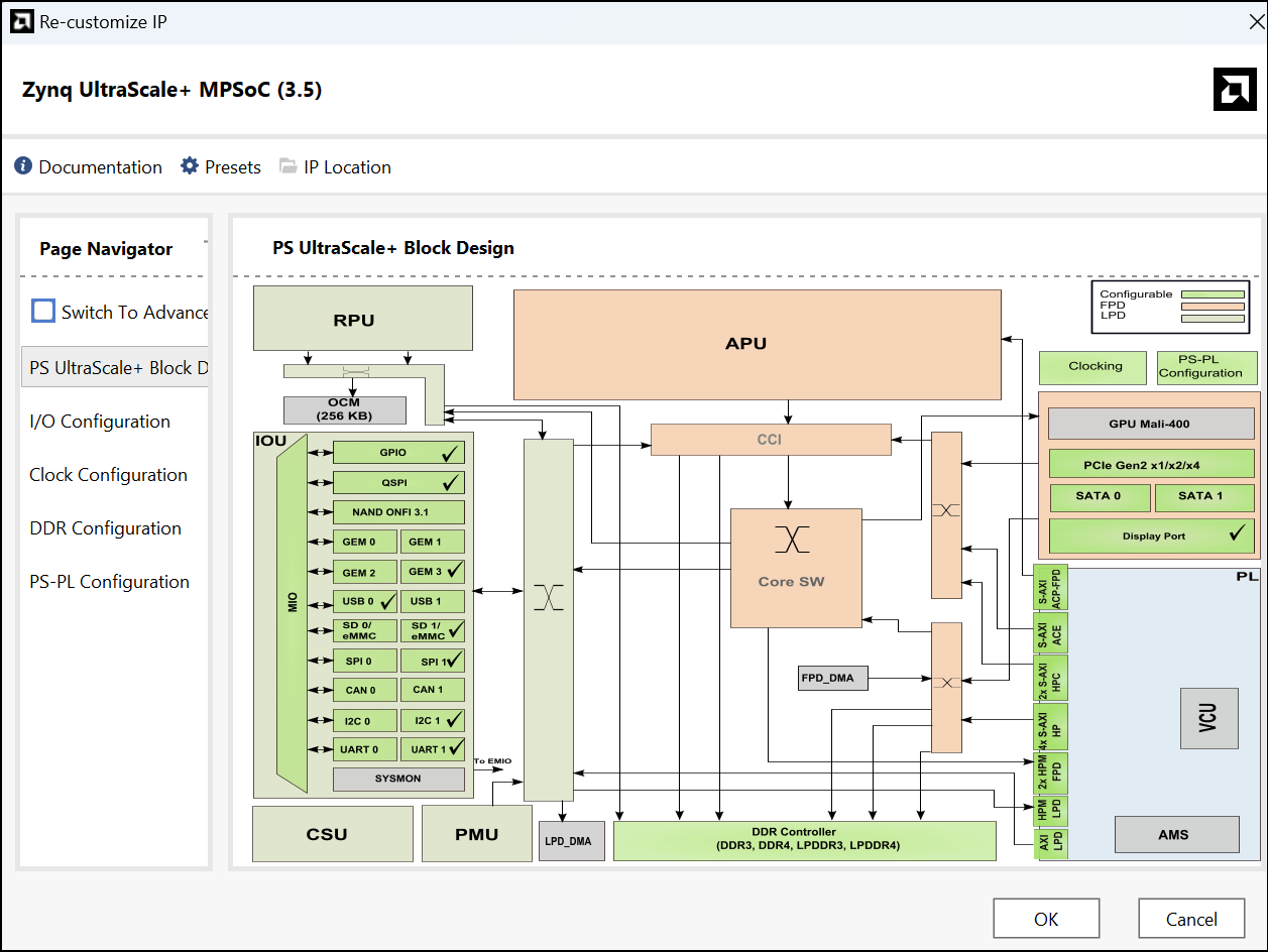
4. Add the required third party IPs or Vivado provided IPs into your block design. Add the below list of IPs to complete the block design:
Clocking Wizard IP
Processor System Reset IP
AXI Interconnect IP
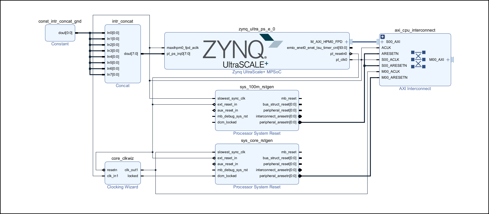
Note that the block design does not contain any information about the HDL IP core.
5. Export the complete block design as a Tcl script. In the Files tab, click Export and select Export Block Design. Name the Tcl script as system.tcl.
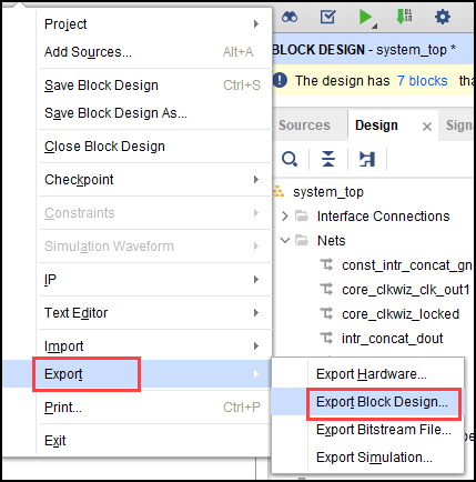
The exported Tcl script contains the custom reference design. You use the Tcl script to recreate the block design and integrate the HDL IP core with the block design in a Xilinx Vivado project.
After exporting the custom reference design to the Tcl script, you can create these custom board files in MATLAB:
The board definition file (
plugin_board.m)The board registration file (
hdlcoder_board_customization)The reference design definition file (
plugin_rd.m)The reference design registration file (
hdlcoder_ref_design_customization)
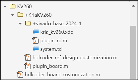
The figure shows the folder structure for custom board and reference design files. After creating these files, add folder to the MATLAB path before generating IP Core.
Register AMD Kria KV260 Vision AI Starter Kit with the HDL Coder
To register the AMD Kria KV260 Vision AI Starter Kit with HDL Coder, create the board definition and board registration files in MATLAB.
Create Board Definition File
Create a board definition file with the name plugin_board.m under the board plugin package folder +KriaKV260. This file contains information about the peripherals present on the board and the corresponding FPGA pin mappings. For more information on the board definition file, see AMD User Guide.
The BoardName property defines the KV260 board name as AMD Kria KV260 Vision AI Starter Kit. This name displays in HDL Workflow Advisor and Configuration Parameter dialog box.
function hB = plugin_board()

%   Copyright 2025 The MathWorks, Inc.

   % Board definition

   % Construct board object
   hB = hdlcoder.Board;
   hB.BoardName    = 'AMD Kria KV260 Vision AI Starter Kit';

   % FPGA device information
   hB.FPGAVendor   = 'Xilinx';
   hB.FPGAFamily   = 'Zynq UltraScale+';
   hB.FPGADevice   = 'xck26-sfvc784-2LV-c';
   hB.FPGAPackage  = '';
   hB.FPGASpeed    = '';

   % Tool information
   hB.SupportedTool = {'Xilinx Vivado'};

   % FPGA JTAG chain position
   hB.JTAGChainPosition = 1;

   % Add interfaces
   % Custom board external I/O interface
   hB.addExternalIOInterface( ...
      'InterfaceID',    'PMOD Connector J2', ...
      'InterfaceType',  'OUT', ...
      'PortName',       'PMOD', ...
      'PortWidth',      8, ...
      'FPGAPin',        {'H12', 'B10', 'E10', 'E12', 'D10', 'D11', 'C11', 'B11'}, ...
      'IOPadConstraint', {'IOSTANDARD = LVCMOS33'});

end
Create Board Registration File
Create a board registration file with the name hdlcoder_board_customization.m. A board registration file contains a list of board plugins. HDL Coder registers boards associated with the board plugin by using the customization file.
function r = hdlcoder_board_customization
% Board plugin registration file
% 1. Any registration file with this name on MATLAB path will be picked up
% 2. Registration file returns a cell array pointing to the location of
%    the board plug-ins
% 3. Board plugin must be a package folder accessible from MATLAB path,
%    and contains a board definition file

%   Copyright 2025 The MathWorks, Inc.

r = { ...
    'KriaKV260.plugin_board', ...
    };
end
Register Custom Reference Design with the HDL Coder Workflow
After registering the Kria KR260 board, you can register the reference design with HDL Coder.
Create Reference Design Definition File
Create a reference design definition file with the name plugin_rd.m. A reference design definition file defines the interface connections between the custom reference design and the HDL IP core that is generated by the HDL Coder.
function hRD = plugin_rd()

%Copyright 2025 The MathWorks, Inc.

% Reference Design definition

% Construct Reference Design object

hRD = hdlcoder.ReferenceDesign('SynthesisTool', 'Xilinx Vivado');

hRD.ReferenceDesignName = 'Default system';
hRD.BoardName = 'AMD Kria KV260 Vision AI Starter Kit';

% Tool information
hRD.SupportedToolVersion = {'2024.1'};

%
hRD.addCustomVivadoDesign( ...
    'CustomBlockDesignTcl', 'system.tcl', ...
    'VivadoBoardPart','xilinx.com:KV260_som:part0:1.4');

%Design constraints
hRD.CustomConstraints = {'kria_kv260.xdc'};


%% Add interfaces
% add clock interface
hRD.addClockInterface( ...
    'ClockConnection',   'core_clkwiz/clk_out1', ...
    'ResetConnection',   'sys_core_rstgen/peripheral_aresetn');

% add AXI4 and AXI4-Lite slave interfaces
hRD.addAXI4SlaveInterface( ...
    'InterfaceConnection', 'axi_cpu_interconnect/M00_AXI', ...
    'BaseAddress',         '0x00A0000000', ...
    'MasterAddressSpace',  'zynq_ultra_ps_e_0/Data');

%%

% Default devicetree available on the board
hRD.DeviceTreeName = 'system.dtb';

%Enabling the download mode as there is processing system in the design
hRD.HasProcessingSystem = true;


end
The reference design plugin folder, +vivado_base_2024_1, must also contain the design files, such as, system.tcl, that you export from the Xilinx Vivado project. The reference design definition file plugin_rd.m uses the addCustomVivadoDesign function to identify the SoC design project.
If you want to add design specific constraints, add them to the file kria_kv260.xdc and then add this file to the reference design plugin by using the hRD.CustomConstraints property. For more information about KV260 board constraints, see AMD's website.
The reference design definition file also defines the interface connections between the custom reference design and the HDL IP core by using the addClockInterface and addRegisterInterface functions.
Create reference design registration file
Create a reference design registration file named hdlcoder_ref_design_customization.m that contains a list of reference design plugins associated with the KV260 kit. A reference design registration file must also contain the name of the associated board.
function [rd, boardName] = hdlcoder_ref_design_customization

%Copyright 2025 The MathWorks, Inc.

rd = {'KriaKV260.vivado_base_2024_1.plugin_rd', ...

     };

boardName = 'AMD Kria KV260 Vision AI Starter Kit';

end
Setup the AMD Kria KV260 Vision AI Starter Kit
To learn more about the AMD Kria KV260 Vision AI Starter Kit, see the AMD User Guide. To set up the AMD Kria KV260 Vision AI Starter Kit on the board:
1. Connect the shared JTAG or UART port on the board to your computer.
2. Connect the AMD Kria KV260 Vision AI Starter Kit to your computer by using an Ethernet cable.
3. Download the Kria KV260 Linux image, extract the ZIP archive, and copy the contents to the microSD card.
4. Insert the microSD card into the J11 connector and power on the board.
5. Initially, the board uses the factory-provided BIN file to boot up. After the board boots, run this command at Linux terminal of the board to load the provided MathWorks BOOT.BIN file. For more information on opening the Linux terminal on the target, see Command Line Session with AMD SoC Devices (Embedded Coder).
sudo xmutil bootfw_update -i /mnt/BOOT.BIN
6. To apply the changes, reset the board by using the SW2 reset button. The board boots up with the MathWorks BOOT.BIN file.
7. Ping the board at the 192.168.1.101 IP address. This is the IP address that the MathWorks Linux image uses. You can modify this IP address by updating the interfaces file in the /mnt directory.
Generate HDL Code and IP Core
You can now use the board and reference design plugins to generate the HDL IP core, integrate the IP core into the Vivado project, generate the bitstream, and program the Kria board. For more information, see Get Started with IP Core Generation from Simulink Model.
1.1. Add the board and reference design plugins to the MATLAB path. Run these commands in the MATLAB Command Window:
example_root = hdlcoder_amd_examples_root
addpath(example_root,"KV260")
2. Set the Xilinx Vivado tool path by using the hdlsetuptoolpath function. Use your own Xilinx Vivado installation path. For more information, see hdlsetuptoolpath.
hdlsetuptoolpath('ToolName','Xilinx Vivado','ToolPath','vivado_installation_path');
3.Open the Simulink model.
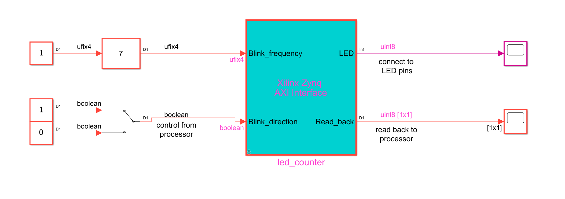
open_system('hdlcoder_led_blinking_8bit');
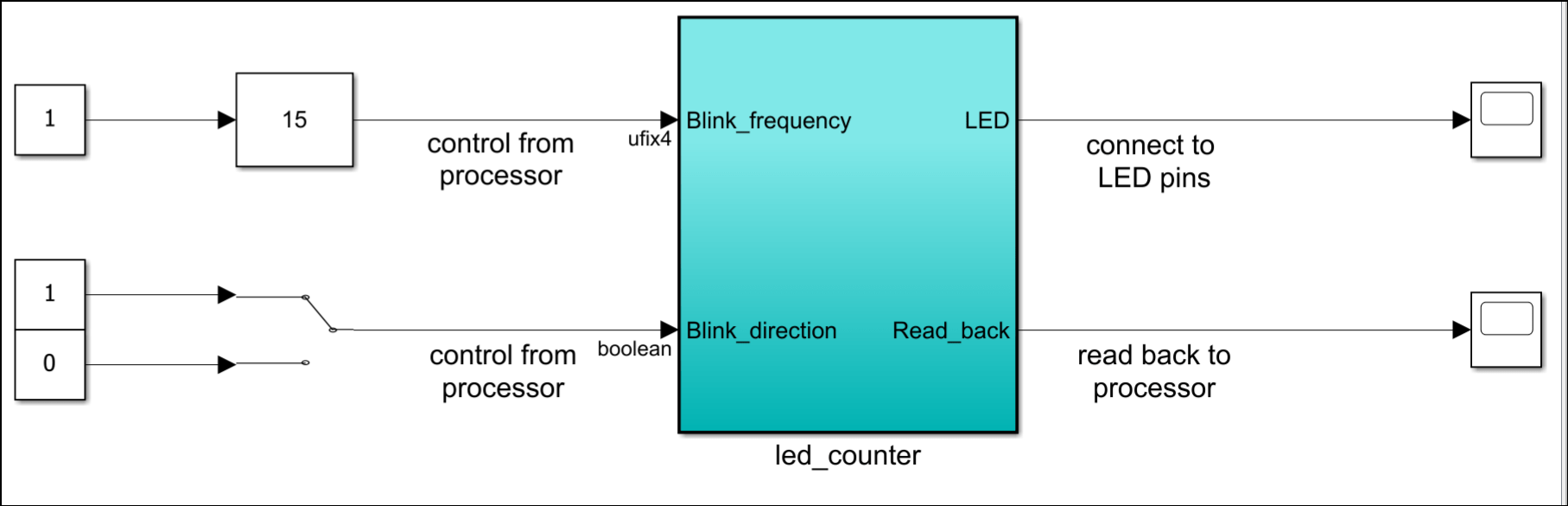
The design under test (DUT) subsystem, led_counter, models a counter that blinks the LEDs on an FPGA board. It has two input ports, Blink_frequency and Blink_direction, which determine the LED blink frequency and direction. The output ports, LED, connects to the user-defined LEDs on the board. The output port Read_back outputs the count value. The board processor sends this value to MATLAB.
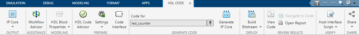
4. Launch HDL Workflow Advisor. In the Apps tab, click HDL Coder. In the HDL Code tab, click on Workflow Advisor.
5. In the task 1.1 Set Target Device and Synthesis Tool, select Target workflow as IP Core Generation. Set Target Platform to AMD kria KV260 Vision AI Starter Kit. Click Run This Task.
6. In the task 1.2 Set Target Reference Design, select Reference design to Default system and click Run This Task.
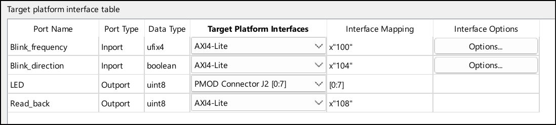
7. In Task 1.3 Set Target Interface, set the target platform interfaces for input and output ports. Set the Blink_frequency, Blink_direction, and Read_back ports to AXI4-Lite and LED port to PMOD Connector J2 [0:7] and then click Run This Task.
8. The registers mapped to the DUT inports, Blink_frequency and Blink_direction, are write registers. If you want to read the values stored in the write registers by using devmem, select Enable readback on write registers check box in task 3.2 Generate HDL IP Core. Right click the task 3.2 Generate HDL IP Core and select Run to selected task. After successful IP Core generation, Code Generation Report opens. Click IP Core Generation Report to see the register address mapping for your DUT ports. For more information, see Custom IP Core Report.
10. To integrate the generated HDL IP Core into your reference design, click task 4.1 Create Project. After task completes, click on the Vivado project link and you can see the generated IP Core inserted in to the Xilinx Vivado reference design.
11. After successful Vivado project creation, click task 4.2 Generate Software Interface. Select Generate Simulink software interface model and run the task. You can see the gm_hdlcoder_led_blinking_interface_8bit.slx. Save this model in your working directory.
12. Generate the bitstream by clicking task 4.3 Build FPGA Bitstream.
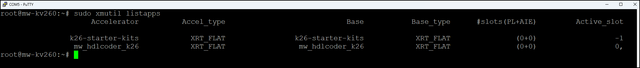
13. After generating bitstream, you can click task 4.4 Program Target Device to program the target device. This task creates an application named mw_hdlcoder_K26 on the target and loads the design onto the FPFA.
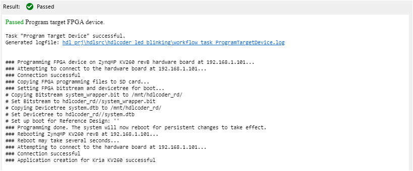
To check whether the application was created on the target, use this Kria utility command:
Verify Design Using Software Interface Model
Open the generated software interface model gm_hdlcoder_led_blinking_interface_8bit.slx. Click Monitor & Tune and you can see the counter value in the scope connected to the Read_back port. For more information, see Get Started with IP Core Generation from Simulink Model.
Control the AXI4-Lite Registers by Using the devmem Command
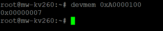
In the above model, the Blink_frequency is 7. You can verify this on the target by using the devmem command. The register address for Blink_frequency is 0xA0000100, which is the base address, 0xA0000000, combined with the address offset, 0x00000100. The base address is the value you defined for your HDL IP core in the plugin_rd.m file. The address offset is the address that HDL Coder assigns to this register in Interface Mapping tab. You can also view this information in the IP core generation report.
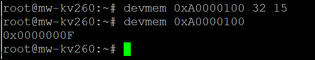
You can also change the blink frequency by using the devmem command. Change the frequency to 15.
You can follow the same process to create custom board and custom reference design for KR260 using HDL Coder. For more information, see Define Custom Board and Reference Design for AMD Kria KR260 Robotics Kit.
See Also
Register a Custom Board | Register a Custom Reference Design