Valve Plate Orifice (IL)
R2026bVariable orifice in an isothermal axial-piston machine
Valve Plate Orifice (IL) block

To add a block to a model, double-click the canvas and start typing the block name. Then, select the block from the list.
Libraries:
Simscape /
Fluids /
Isothermal Liquid /
Pumps & Motors /
Auxiliary Components
Description
The Valve Plate Orifice (IL) block models a crescent-shaped opening between moving pistons and a pump in an axial-piston machine. The rotating pistons periodically connect to the pump intake or discharge through the orifice plate. You can connect two valve plate blocks to each cylinder of an axial-piston pump to represent both the pump inlet and outlet slots.
A rotating cylinder, with one crescent slot, is connected to the pump intake at port A and pump discharge at port B. These points are connected to the plate between the Pressure carryover angle and radians (180 degrees) from each other. The plate rotation angle is set by the signal at port G. The cylinder position angle, γ, is the sum of the position signal, G, and the initial angle offset, the Phase angle, γ0:
γ is always between 0 and 2π. For any combined signal and offset larger than 2π rad, γ is maintained at 2π, and for any combined signal and offset lower than 0 rad, and γ is maintained at 0. To change the initial position of the orifice relative to the slot, you can adjust the Phase angle parameter.
Axial-Piston Machine With Five Pistons
The numbers in the diagram indicate the components of an axial-piston machine:
Valve plate orifice
Rotor
Piston
Driving shaft
Swash plate
Cylinder Angle
The cylinder rotational alignment with the slot is described by the following angles:
Cylinder angle at rotation onto slot, γ1:
Cylinder angle at complete rotation onto slot, γ2:
Cylinder angle at rotation beyond slot, γ3:
Cylinder angle at complete rotation beyond slot, γ4:
where:
Ψ is the Pressure carryover angle. This angle represents the average angular distance the piston travels during its pressure transition period from a closed to opened slot.
r is the half of the Cylinder orifice diameter.
R is the Cylinder block pitch radius.
Orifice Opening Area
Orifice area calculations during cylinder motion
The transition opening area, which is the opening between the cylinder rotation angles γ1 and γ2, is calculated as:
The transition closing area, which is the opening between the cylinder rotation angles γ3 and γ4, is calculated as:
where the opening and closing parameters are:
and
The area between γ2 and γ3 is and the area between γ4 and γ1 is The maximum opening of the orifice is
A nonzero Smoothing factor can provide additional numerical stability when the orifice is in near-closed or near-open position.
Numerically-Smoothed Orifice Angle
At the orifice slot entrance and exit angles, you can maintain numerical robustness in your simulation by adjusting the block Smoothing factor parameter. If the Smoothing factor parameter is nonzero, the block smoothly saturates the transition opening angle between γ1 and γ2 and the transition closing angle between γ3 and γ4. For more information, see Numerical Smoothing.
Mass Flow Rate Equation
The flow through a valve plate orifice is calculated from the pressure-area relationship:
where:
Cd is the Discharge coefficient.
Aorifice is the area open to flow.
is the average fluid density.
Δp is the pressure drop over the valve, PA – PB.
The critical pressure difference, Δpcrit, is the pressure differential associated with the Critical Reynolds number, Recrit, which is the point of transition between laminar and turbulent flow in the fluid:
Examples
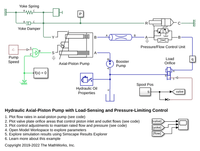
Hydraulic Axial-Piston Pump with Load-Sensing and Pressure-Limiting Control
A test rig designed to investigate the interaction between an axial-piston pump and a typical control unit simultaneously performing the load-sensing and pressure-limiting functions. To increase the fidelity of the simulation, this example uses a detailed model of the pump that accounts for the interaction between the pistons, swash plate, and valve plate.
Ports
Conserving
Input
Parameters
Extended Capabilities
Version History
Introduced in R2020a

