Control PMSM Loaded with Dual Motor (Dyno)
This example uses field-oriented control (FOC) to control two three-phase permanent magnet synchronous motors (PMSM) coupled in a dyno setup. Motor 1 runs in the closed-loop speed control mode. Motor 2 runs in the torque control mode and loads Motor 1 because they are mechanically coupled. You can use this example to test a motor in different load conditions.
The example simulates two motors that are connected back-to-back. You can use a different speed reference for Motor 1 and a different torque reference for Motor 2 (derived from the magnitude and electrical position of the Motor 2 reference stator current). Motor 1 runs at the reference speed for the load conditions provided by Motor 2 (with a different torque reference).
These equations describe the computation of d-axis and q-axis components of the Motor 2 reference stator current.

where:
 is the
 d-axis component of the Motor 2 reference stator current.
 is the
 q-axis component of the Motor 2 reference stator current.
 is the magnitude of the Motor 2 reference stator current.
 is the electrical position of the Motor 2 reference stator current.
The example runs in the controller hardware board. You can input the speed reference for Motor 1 and current reference for Motor 2 using a host model. The host model uses serial communication to communicate with the controller hardware board.
Current control loops in Motor 1 and Motor 2 control algorithms are offset by Ts/2, where Ts is the control-loop execution rate.
Models
The example includes the model mcb_pmsm_foc_f28379d_dyno.
You can use this model for both simulation and code generation.

Required MathWorks Products
To simulate model:
Motor Control Blockset™
To generate code and deploy model:
Motor Control Blockset™
Embedded Coder®
C2000™ Microcontroller Blockset
Fixed-Point Designer™ (only needed for optimized code generation)
Prerequisites
1. Obtain the motor parameters for both Motor 1 and Motor 2. We provide default motor parameters with the Simulink® model that you can replace with the values from either the motor datasheet or other sources.
However, if you have the motor control hardware, you can estimate the parameters for the motor that you want to use, by using the Motor Control Blockset™ parameter estimation tool. For instructions, see Estimate Motor Parameters Using Motor Control Blockset Parameter Estimation Tool.
2. Update the motor parameters (that you obtained from the datasheet, other sources, or parameter estimation tool) and inverter parameters in the model initialization script associated with the Simulink® model. For instructions, see Estimate Control Gains and Tune Control Parameters.
For this example, update the motor parameters for both the motors in the model initialization script.
Simulate Model
This example supports simulation. Follow these steps to simulate the model.
1. Open a model included with this example.
2. Click Run on the Simulation tab to simulate the model.
3. Click Data Inspector on the Simulation tab to view and analyze the simulation results.
4. Input a different speed reference for Motor 1 and a different current reference (load) for Motor 2. Observe the measured speed and other logged signals in the Data Inspector.
Generate Code and Deploy Model to Target Hardware
This section instructs you to generate code and run the FOC algorithm on the target hardware.
The example uses a host and a target model. The host model is a user interface to the controller hardware board. You can run the host model on the host computer. The prerequisite to use the host model is to deploy the target model to the controller hardware board. The host model uses serial communication to command the target Simulink® model and run the motor in a closed-loop control.
Required Hardware
The example supports this hardware configuration. You can also use the target model name to open the model for the corresponding hardware configuration, from the MATLAB® command prompt.
LAUNCHXL-F28379D controller + 2 BOOSTXL-DRV8305 inverters:
mcb_pmsm_foc_f28379d_dyno
LAUNCHXL-F28379D controller + 2 BOOSTXL-3PHGANINV inverters:
mcb_pmsm_foc_f28379d_dyno
For connections related to the preceding hardware configuration, see Instructions for Dyno (Dual Motor) Setup.
Generate Code and Run Model on Target Hardware
1. Simulate the target model and observe the simulation results.
2. Complete the hardware connections.
3. The model automatically computes the ADC (or current) offset values. To disable this functionality (enabled by default), update the value 0 to the variable inverter.ADCOffsetCalibEnable in the model initialization script.
Alternatively, you can compute the ADC offset values and update it manually in the model initialization scripts. For instructions, see Run 3-Phase AC Motors in Open-Loop Control and Calibrate ADC Offset.
4. Compute the quadrature encoder index offset value and update it in the model initialization scripts associated with the target model. For instructions, see Quadrature Encoder Offset Calibration for PMSM.
For this example, update the QEP offset values in the pmsm_motor1.PositionOffset and pmsm_motor2.PositionOffset variables in initialization script.
5. Open the target model. If you want to change the default hardware configuration settings for the model, see Model Configuration Parameters.
6. To ensure that CPU2 is not mistakenly configured to use the board peripherals intended for CPU1, load a sample program to CPU2 of LAUNCHXL-F28379D, for example, a program that operates the CPU2 blue LED by using GPIO31 (c28379D_cpu2_blink.slx). For more information about the sample program or model, see the Task 2 - Create, Configure and Run the Model for TI Delfino F28379D LaunchPad (Dual Core) section in Getting Started with Texas Instruments C2000 Microcontroller Blockset (C2000 Microcontroller Blockset).
7. Click Build, Deploy & Start on the Hardware tab to deploy the model to the hardware.
8. Click the mcb_pmsm_foc_host_model_dyno.slx host model hyperlink in the target model to open the associated host model.
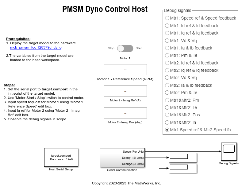
9. In the model initialization script associated with the target model, specify the communication port using the variable target.comport. The example uses this variable to update the Port parameter of the Host Serial Setup, Host Serial Receive, and Host Serial Transmit blocks available in the host model.
10. Click Run on the Simulation tab to run the host model.
11. Change the position of the Start / Stop Motor 1 switch to On, to start running the motor.
12. Update the Motor 1 - Reference Speed (RPM), Motor 2 - Imag Ref (A), and Motor 2 - Imag Pos (deg) in the host model.
Note: Be cautious when using values other than 90 or 270 degrees in the Motor 2 - Imag Pos (deg) field. These values generate current along the d-axis that creates a magnetizing effect. Excess current along the d-axis can create saturation and can damage the motor magnets.
13. Select the debug signals that you want to monitor, to observe them in the Time Scope block of host model.
Other Things to Try
You can also use SoC Blockset™ to develop a real-time motor control application for a dual motor setup that utilizes multiple processor cores to obtain design modularity, improved controller performance, and other design goals. For details, see Partition Motor Control for Multiprocessor MCUs.