Fuel Cell
Fuel cell electrical system
Libraries:
Simscape /
Electrical /
Sources
Description
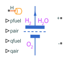
The Fuel Cell block models a fuel cell that converts the chemical energy of hydrogen into electrical energy.
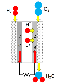
This chemical reaction defines the electrical conversion:
which occurs due to these anode and cathode half-reactions:
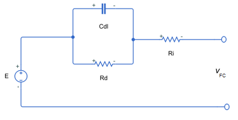
A fuel cell stack comprises several series-connected fuel cells. This figure shows the equivalent circuit of a single fuel cell that this block uses
where:
VFC is the cell voltage.
Ri is the Nominal internal resistance.
Rd is the Sum of activation and concentration resistances.
Cdl is the parallel RC capacitance that accounts for time dynamics in the cell.
Equations
You can use the Model fidelity parameter to set the Fuel Cell block to two different levels of fidelity:
Simplified - nominal conditions— The block calculates the Nernst voltage at the nominal condition of temperature and pressure.Detailed with physical inputs— The block calculates the Nernst voltage by considering the pressures and flow rates of fuel and air.
When Model fidelity is set to Simplified - nominal
conditions, the Fuel Cell block
calculates the Nernst voltage, E, at the nominal condition of
temperature and pressure, as defined by these equations:
where:
Eoc is the Nominal open-circuit voltage.
N is the Number of cells per stack.
iFC is the current that the fuel cell generates.
vFC is the voltage across the fuel cell terminals.
Nunit is the Number of stacks in module (series).
vd is the voltage drop that accounts for fuel cell dynamics.
A is the Tafel slope, in volts.
i0 is the Exchange current.
.
When Model fidelity is set to Detailed with physical
inputs, the Fuel Cell block
calculates the Nernst voltage, E, by considering the
pressures and flow rates of fuel and air.
These equations determine the rates of utilization of hydrogen, UH2, and oxygen, UO2
where:
N is the Number of cells per stack.
iFC is the current that the fuel cell generates.
R is the universal gas constant.
T is the operating temperature of the fuel cell.
F is the Faraday's constant.
pfuel is the supply pressure of the fuel, in
bar.qfuel is the fuel flow rate.
xH2 is the concentration of hydrogen in the fuel, in percent.
pair is the supply pressure of air, in
bar.qair is the air flow rate.
xO2 is the concentration of oxygen in the air, in percent.
These equations define the partial pressures:
where xH2O is the concentration of vapor in air, in percent.
Then, the block computes the fuel cell voltage as
where:
.
is the electrokinetic term for the activation.
is the Tafel slope as a function of the temperature.
T is the operating temperature of the fuel cell.
Tnom is the value of the Nominal temperature parameter.
is the electrokinetic term for the concentration.
F is the Faraday constant.
R is the universal gas constant.
pnH2 is the nominal hydrogen pressure, in
bar.pnO2 is the nominal oxygen pressure, in
bar.ilim is the minimum value between:
The value of the Collapse current parameter.
The maximum current possible with the fuel flowrate qfuel:
The maximum current possible with the air flowrate qair:
The block computes the power dissipated, or the heat released in the fuel cell, by using this equation:
Variables
To set the priority and initial target values for the block variables before simulation, use the Initial Targets section in the block dialog box or Property Inspector. For more information, see Set Priority and Initial Target for Block Variables.
Use nominal values to specify the expected magnitude of a variable in a model. Using system scaling based on nominal values increases the simulation robustness. Nominal values can come from different sources. One of these sources is the Nominal Values section in the block dialog box or Property Inspector. For more information, see System Scaling by Nominal Values.
Examples

Analyze Fuel Cell Performance
A Fuel Cell block with nominal parameters that operates at constant voltage and varying fuel flow rates at different hydrogen pressures. The power delivered varies as a function of the hydrogen pressure.

Validate Fuel Cell I-V Characteristic
This model represents a harness for the validation of fuel cell (FC) parameters. This example extracts I-V and power characteristic curves from the model at controlled conditions and compares them to a datasheet. The datasheet also contains specific properties such as the stack size, limiting current, and the flow rates of hydrogen and air.
Limitations
The Fuel Cell block does not allow electrolysis.
Ports
Input
Conserving
Parameters
Main
Level of fidelity of the fuel cell model.
Nominal open-circuit voltage.
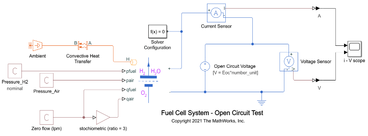
When the amount of flow is very low or close to zero and the values of the fuel and air pressures are equal to their nominal values, the output voltage of the fuel cell is equal to the nominal open-circuit voltage multiplied by the number of module units. The current that flows out of the fuel cell is negligible. This figure shows how to set the open-circuit test:
Amount of overpotential required to increase the reaction rate by a factor ten.
Nominal internal resistance.
Exchange current at the nominal temperature.
At the nominal exchange current, the fuel cell leaves the region of activation polarization and enters the region of ohmic polarization.
Value of current at which the fuel cell voltage becomes zero. As the fuel cell enters the region of concentration polarization and the current continues to increase, the voltage starts decreasing at a faster rate.
Dependencies
To enable this parameter, set Model fidelity
to Detailed with physical inputs.
Number of cells per stack.
The cell count value in this block is consistent with the fuel cell delivering its maximum output power for specified set points of flow and H2 pressure.
Stack of module units in series.
Stack module in series to scale up voltage. For example, 10 module units in series with an open-circuit voltage of 65 V deliver a voltage of 650V.
Supply
To enable these parameters, in the Main tab, set Model
fidelity to Detailed with physical
inputs.
Hydrogen gauge pressure at nominal temperature.
Dependencies
To enable this parameter, set Model fidelity
to Detailed with physical inputs.
Oxygen gauge pressure at nominal temperature.
Dependencies
To enable this parameter, set Model fidelity
to Detailed with physical inputs.
Molar fraction concentration of hydrogen in fuel, in percent.
Dependencies
To enable this parameter, set Model fidelity
to Detailed with physical inputs.
Molar fraction concentration of oxygen in fuel, in percent.
Dependencies
To enable this parameter, set Model fidelity
to Detailed with physical inputs.
Molar fraction concentration of vapor in air, in percent.
Dependencies
To enable this parameter, set Model fidelity
to Detailed with physical inputs.
Dynamics
Whether to model the activation delay of the fuel cell.
Sum of the activation resistance and concentration resistance.
Dependencies
To enable this parameter, set Model activation
delay to Yes.
Time constant.
Dependencies
To enable this parameter, set Model activation
delay to Yes.
Thermal
To enable these parameters, in the Main tab, set Model
fidelity to Detailed with physical
inputs.
Temperature at which the nominal parameters are measured.
Dependencies
To enable this parameter, set Model fidelity
to Detailed with physical inputs.
Thermal mass associated with the thermal port, H. This value represents the energy required to raise the temperature of the thermal port by one degree.
Dependencies
To enable this parameter, set Model fidelity
to Detailed with physical inputs.
References
[1] Do, T.C., et al. “Energy Management Strategy of a PEM Fuel Cell Excavator with a Supercapacitor/Battery Hybrid Power Source”. Energies 12, no. 22, (November 2019). DOI.org (Crossref), doi:10.3390/en13010136.
[2] Motapon, Souleman N., O. Tremblay and L. Dessaint, “A generic fuel cell model for the simulation of fuel cell vehicles.” 2009 IEEE Vehicle Power and Propulsion Conference, Dearborn, MI, 2009, pp. 1722-1729, doi: 10.1109/VPPC.2009.5289692
[3] Hirschenhofer, J. H.,, D.B. Stauffer, R.R. Engleman, and M.G. Klett. Fuel Cell Handbook (4th Ed). U.S. Department of Energy Office of Fossil Energy, 1988.
[4] Larminie, James, and Andrew Dicks. Fuel Cell Systems Explained. West Sussex, England: John Wiley & Sons, Ltd,., 2003. https://doi.org/10.1002/9781118878330.
Extended Capabilities
Version History
Introduced in R2021a