Generate Structured Text Code for Subsystem Reference Blocks
R2026bThis example shows how to generate Structured Text code for a model that uses Subsystem reference blocks for distributed code generation. In this example, each referenced subsystem represents an independently developed component. You generate code for the top-level subsystem and each referenced subsystem separately and then integrate the generated function blocks in your PLC IDE.
In large PLC projects, separate teams work on individual components and their control logic. You can design, simulate, and test these independent subsystems before integration by using Subsystem Reference blocks for each component.
In this example you:
Specify the Subsystem Reference blocks in the model as externally defined
Generate code for the top-level subsystem
Generate code for the referenced subsystems
Open and Examine the Model
Open the model.
open_system("mSubSysRefSystemIntegration");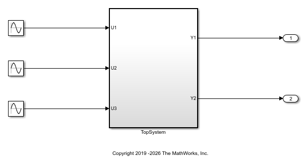
The model contains a top-level atomic subsystem, TopSystem, that has three input ports U1, U2, and U3, and two output ports, Y1 and Y2.
The TopSystem subsystem contains three referenced subsystems, SubSystem1, SubSystem2, and SubSystem3.
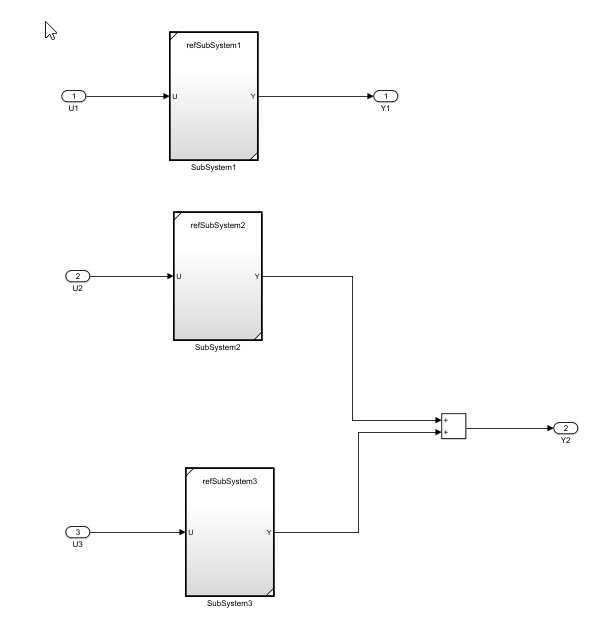
Each referenced subsystem is a separate Simulink® model that you can open, edit, and test independently.
Specify Subsystem Blocks as Externally Defined
To specify that a subsystem block is externally defined, specify the block names in the Externally Defined Identifiers configuration parameter. Specify that a subsystem block is externally defined, by either:
Programmatically specifying the block names in the
PLC_ExternalDefinedNamesparameter. For example to specify the subsystems in this example as externally defined, enter:
cs = getActiveConfigSet("mSubSysRefSystemIntegration");
set_param(cs,"PLC_ExternalDefinedNames","SubSystem1, SubSystem2, SubSystem3")
Specifying the subsystem block names in the Externally defined identifiers model PLC code generation parameter. In the PLC Code tab, click Settings. In the Configuration Parameters dialog box, click PLC Code Generation > Interface and specify the subsystem names in the Externally defined identifiers parameter.
Generate Structured Text Code for Top-Level Subsystem
First, copy the refSubSystem1, refSubsystem2, refSubSystem3, SSRefSubSystem1, SSRefSubSystem2, SSRefSubSystem3, and mSubSysRefSystemIntegration model files to the same folder location.
Generate code for the top-level subsystem, TopSystem. Because the referenced subsystems are external, the generated code contains the DUT subsystem, but does not include the Simulink models associated with the referenced subsystem.
For this example, you generate code for the CODESYS 3.5 IDE. To generate code, select the TopSystem subsystem and in the PLC Code tab, click Settings. In the Configuration Parameters dialog box, in the left pane, click PLC Code Generation Settings. Set the Target IDE parameter to CODESYS 3.5. Click OK. Click Generate PLC Code.
Alternatively, you can generate code by using the plcgeneratecode function.
generatedfiles = plcgeneratecode("mSubSysRefSystemIntegration/TopSystem");### Generating PLC code for 'mSubSysRefSystemIntegration/TopSystem'. ### Using model settings from 'mSubSysRefSystemIntegration' for PLC code generation parameters. ### Begin code generation for IDE CODESYS 3.5 (codesys35). ### Emit PLC code to file. ### Creating PLC code generation report index.html. ### PLC code generation successful for 'mSubSysRefSystemIntegration/TopSystem'. ### Generated files: plcsrc/mSubSysRefSystemIntegration.xml
View the generated Structured Text code for the TopSystem Subsystem block. The generated code contains a FUNCTION_BLOCK definition for the TopSystem subsystem block and instance variable declarations for the referenced subsystems but it contains no function block definitions.
file = fullfile("plcsrc/mSubSysRefSystemIntegration.st")file = "plcsrc/mSubSysRefSystemIntegration.st"
coder.example.extractLines(file,"FUNCTION_BLOCK TopSystem","VAR_TEMP",1,0)
FUNCTION_BLOCK TopSystem
VAR_INPUT
    ssMethodType: SINT;
    U1: LREAL;
    U2: LREAL;
    U3: LREAL;
END_VAR
VAR_OUTPUT
    Y1: LREAL;
    Y2: LREAL;
END_VAR
VAR
    i0_SubSystem1: SubSystem1;
    i0_SubSystem2: SubSystem2;
    i0_SubSystem3: SubSystem3;
END_VAR
To generate the function block definitions you must individually generate code for each referenced subsystem and import and integrate the code in the target IDE.
Generate Code for the Referenced Subsystem Blocks
Next, you must generate code for each referenced subsystem and import the generated Structured Text code in your target IDE. For example, to generate code for the SubSystem1 block, open the SSrefSubSystem1.slx file and generate code for the top-level SubSystem1 block.
Double-click a Subsystem reference block to open the model. To set the target IDE, in the PLC Code tab, click Settings. In the Configuration Parameters dialog box, in the left pane click PLC Code Generation Settings. Set the Target IDE parameter to CODESYS 3.5. Click OK. Click Generate PLC Code. Repeat this step for each referenced subsystem.
Alternatively, you can generate code by using the plcgeneratecode function.
open_system("SSRefSubSystem1")
plcgeneratecode("SSRefSubSystem1/SubSystem1")
### Generating PLC code for 'SSRefSubSystem1/SubSystem1'.
### Using model settings from 'SSRefSubSystem1' for PLC code generation parameters.
### Begin code generation for IDE CODESYS 3.5 (codesys35).
### Emit PLC code to file.
### Creating PLC code generation report index.html.
### PLC code generation successful for 'SSRefSubSystem1/SubSystem1'.
### Generated files:
plcsrc/SubSystem1.xml
View the generate Structured Text code for the SubSystem1 block. The generated code contains a FUNCTION_BLOCK definition with inputs, outputs, internal state variables and computation logic.
file2 = fullfile("plcsrc/SubSystem1.st")file2 = "plcsrc/SubSystem1.st"
coder.example.extractLines(file2,"FUNCTION_BLOCK SubSystem1","END_FUNCTION_BLOCK",1,1)
FUNCTION_BLOCK SubSystem1
VAR_INPUT
    ssMethodType: SINT;
    U: LREAL;
END_VAR
VAR_OUTPUT
    Y: LREAL;
END_VAR
VAR
    UnitDelay_DSTATE: LREAL;
END_VAR
CASE ssMethodType OF
    SS_INITIALIZE:
        (* SystemInitialize for Atomic SubSystem: '<Root>/SubSystem1' *)
        (* SystemInitialize for Atomic SubSystem: '<S1>/RefSubsystem1' *)
        (* InitializeConditions for UnitDelay: '<S2>/Unit Delay' *)
        UnitDelay_DSTATE := 0.0;
        (* End of SystemInitialize for SubSystem: '<S1>/RefSubsystem1' *)
        (* End of SystemInitialize for SubSystem: '<Root>/SubSystem1' *)
    SS_OUTPUT:
        (* Outputs for Atomic SubSystem: '<Root>/SubSystem1' *)
        (* Outputs for Atomic SubSystem: '<S1>/RefSubsystem1' *)
        (* Gain: '<S2>/Gain' incorporates:
         *  Sum: '<S2>/Sum'
         *  UnitDelay: '<S2>/Unit Delay' *)
        Y := (U - UnitDelay_DSTATE) * 0.5;
        (* Update for UnitDelay: '<S2>/Unit Delay' *)
        UnitDelay_DSTATE := Y;
        (* End of Outputs for SubSystem: '<S1>/RefSubsystem1' *)
        (* End of Outputs for SubSystem: '<Root>/SubSystem1' *)
END_CASE;
END_FUNCTION_BLOCK
Repeat the code generation process for the SubSystem2 and SubSystem3 Subsystem blocks. After you generate code for the Subsystem Reference blocks, you then import the generated Structured Text code for the top-level Subsystem block and the Subsystem Reference blocks into your target IDE.

