Tank Robot Control Using VEXnet Gamepad
This example shows you how to use Simulink® Coder™ Support Package for ARM® Cortex®-based VEX® Microcontroller to control 2-wheeled tank robot using a VEX wireless controller.
Introduction
Simulink Coder Support Package for ARM Cortex-based VEX Microcontroller enables you to create and run Simulink models on a VEX microcontroller.
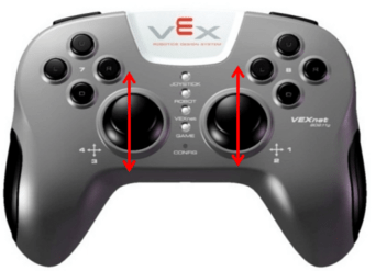
In this example, you will learn how to use a VEX gamepad or controller to drive a 2-wheeled tank robot. The 2 wheels are powered by 2 DC motors which are connected to a VEX microcontroller. The Simulink model will map 2 analog sticks on the gamepad to control the speed of the 2 motors such that when the 2 sticks are pushed up the tank robot will move forward, when pushed back the robot will go reverse, and when pushed in opposite directions it will turn right or left accordingly.
Prerequisites
If you are new to Simulink, we recommend watching the Simulink Quick Start video.
We recommend completing Getting Started with VEX Microcontroller Support Package.
Required Hardware
To run this example you will need the following hardware:
ARM Cortex-based VEX Microcontroller
VEXnet Gamepad and VEXnet keys
Standard DC Motors (2) and Motor Controller 29 (2)
2-wheel robot platform
7.2V Battery
USB type A-Male to A-Male cable
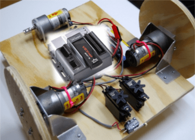
Below is the figure of a simple 2-wheel robot platform with 2 DC motors connected to the 2 wheels and attached to a VEX microcontroller.

Task 1 - Hardware Connections
1. Connect the VEX Microcontroller to your computer with a USB cable.
2. Connect the 2 DC motors to the appropriate motor pins on the VEX Microcontroller. The right motor should be connected to the motor pin 7, and left motor to pin 3. Use the Motor Controller 29 cables to establish the connection between the motors leads and the pins on VEX Microcontroller. Connect them as described on Page 4 of the VEX Microcontroller and VEXnet Joystick User Guide
3. Connect the battery supply to VEX Microcontroller.
Task 2 - Map the Joysticks to the DC Motors for Tank Control
In this task, you will create a Simulink model that configures the two analog sticks on the VEXnet Gamepad to control the 2 DC motors of the robot to obtain tank control. Tank control is achieved when the robot moves forward or backwards when the 2 analog sticks are pushed together up or down respectively and the make turns when pushed in opposite directions.
1. In MATLAB®, select HOME > New > Simulink Model.
2. Open vexarmcortexlib and drag and drop the Gamepad Joystick block twice from the Gamepad library into your Simulink model. Rename the 2 blocks to RightAnalogStick and LeftAnalogStick. Configure the Analog Channel parameter for the two blocks to 2 and 3 to choose the vertical axes on the right and left analog sticks respectively.
3. Drag the DC Motor block twice from the Actuators library to your model and rename them to RightMotor and LeftMotor. Configure only the Motor Channel parameters for the 2 blocks to 7 and 3 to as the pins to which the right and left motors are connected respectively.
4. Connect the output port of the RightAnalogStick to input port of the RightMotor block. Similarly, connect the corresponding ports of the LeftAnalogStick and LeftMotor blocks.
5. Drag a Gain block from the Math Library in the VEX Microcontroller library to your model and insert it between the LeftAnalogStick and LeftMotor blocks. Change the Gain parameter of the block to -1. This block inverts the signal going to the left motor to compensate for the alignment of the motors on the robot. This compensation ensures that the robot moves forward or backwards even though the motors are spinning in the opposite direction when the joystick is pushed together up or down respectively.
6. Save your model.
A pre-configured model vexarmcortex_tankrobot_setup is available.

Task 3 - Build and Download the Simulink Model
In this task, you will open the Simulink model created in Task 2, and build and download it to the VEX microcontroller.
1. Make sure to connect the VEX Microcontroller to your computer with a USB A-Male to A-Male cable.
2. Open the Simulink model created in Task 2.
3. In the Simulink model, go to the Modeling tab and click Model Settings.

4. When the Configuration Parameters page opens up, navigate to the Hardware Implementation pane.
Set the Hardware board to ARM Cortex-based VEX Microcontroller.
In the Target Hardware Resources section, set the Build options to Build, load and run to automatically download the generated binary file on to the connected VEX microcontroller.
5. Navigate to Solver pane and set the Solver to discrete (no continuous states).
6. Click OK.
7. In your Simulink model, go to the Hardware tab and click Build, Deploy & Start. The model will now be deployed to the VEX microcontroller.

8. Disconnect the USB cable from the PC and connect it to the VEX gamepad. Turn on the VEX microcontroller and the gamepad. Drive the tank robot by moving around the two analog sticks along the vertical axes 2 and 3.

A pre-configured model(vexarmcortex_tankrobot_setup) is included for your convenience.
Task 4 - Simulate the Simulink Model
In this task, you will setup your Simulink model for simulation using the simulation blocks from the VEX Microcontroller library.
1. Open vexarmcortex_tankrobot_setup model.
2. Double-click RightAnalogStick block and check the box Add input port for simulation to grow an input simulation port. Similarly, check the box Add input port for simulation for LeftAnalogStick block.
3. Drag two instances of the Variable Input block from Utilities in the VEX Microcontroller library to your model. Connect the output port of one of the instances of the block to input port of the LeftAnalogStick. Similarly, connect the other one to the RightAnalogStick.
4. Drag two instances of the Constant block from Utilities in the VEX Microcontroller library to your model. Connect the output port of each Constant block to input port of the Variable Input block.
5. Drag two instances of the Display block from Utilities in the VEX Microcontroller library to your model. Connect the input port of each Display block to speed port of the DC Motor block.
6. Drag the Field Simulator block from Utilities in the VEX Microcontroller library to your model. Connect the input ports to speed output ports of the DC Motor blocks.
7. In the Simulation tab, set the Stop time to inf.

8. Hit the Run button to begin the simulation.
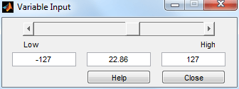
9. Open the Variable Input blocks by double-clicking to access the slider inputs. Move the sliders to simulate the signal of vertical axes 2 and 3 of the analog sticks. Observe the speed values change in the Display blocks s the sliders are moved.

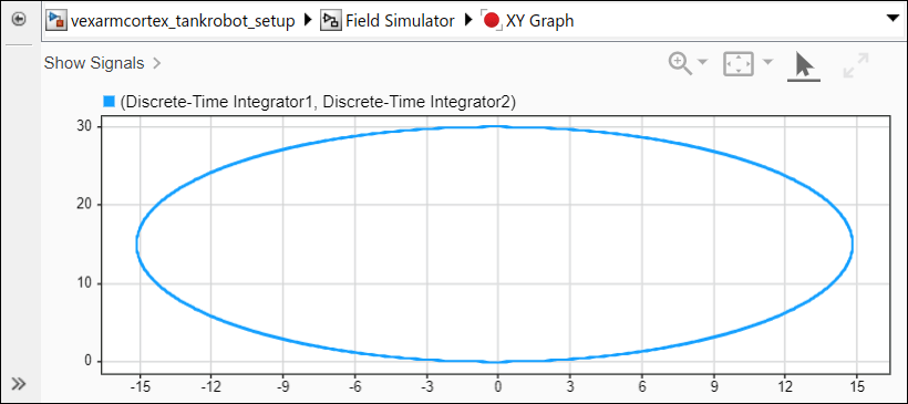
10. Click on Field Simulator block and press Ctrl+U to view the output on XY Graph as shown in the screen below.

A tank robot model with simulation blocks(vexarmcortex_tankrobot) is available for your convenience.
Other Examples
Below are other example models using the 2-Wheel Tank Robot configuration.
1. Use vexarmcortex_tankrobot_withGear model to control the motors' speed using the Gear Transmission block which is built using Stateflow®.
2. Use vexarmcortex_tankrobot_halfSpeed_MLfcn model to switch between half and full speed by click of a button on the VEX gamepad. The logic to switch between the 2 states is built using a MATLAB function block.
More example models using the Get Analog Stick and SetMotor blocks
1. Use vexarmcortex_arcaderobot model to configure the 2-Wheel robot in arcade or skidsteer mode. In this mode, you can drive the robot using just 1 analog stick instead of 2. Move the analog stick along the vertical axis to drive the robot forward and backward, and along the horizontal axis to make turns.
2. Use vexarmcortex_tankrobot_withGear model to control the motors' speed of an arcade robot using the Gear Transmission block which is built using Stateflow.