Network Managed DC-DC Power Converter
This example shows how to manage the asynchronous network commands to a high-speed, closed-loop DC-DC buck converter control algorithm executing the C2000 processor by using the Arm Cortex-M processor. In the TMS320F28388D and similar processor families, the C2000 processors execute the hard-realtime portions of the algorithm and use peripherals, such as ADC and PWM. In contrast, the Arm Cortex-M processor manages the high-level asynchronous communication, such as UDP or TCP, that connect the MCU to external systems. This example implements a technique that extends the DC-DC buck converter in the C2000 DC-DC Buck Converter Using MCU example. You can apply this technique to any design in which a hard-realtime process executes on the C2000 MCU and a high-level asynchronous communication executes on the Arm Cortex-M processor.
Requirements
Controller with Connection to Arm Cortex-M
This model shows a DC-DC buck converter with a voltage-tracking control algorithm executing on the C2000 processor. The Arm Cortex-M processor sends the voltage reference signal to the C2000 processor using an Interprocess Data Read (SoC Blockset), Interprocess Data Channel (SoC Blockset), and Interprocess Data Write (SoC Blockset) block triplet. Similarly, the C2000 processor sends the measured voltage to the Arm Cortex-M processor. To open this model, run the following code.
open_system("soc_dcdc_buck_target");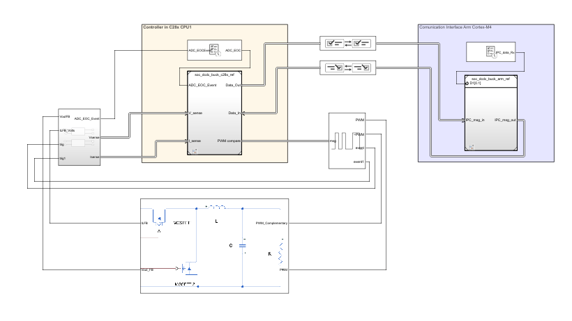
For more information about designing the closed-loop control algorithm and simulating the power daughter board, see C2000 DC-DC Buck Converter Using MCU.
Simulation
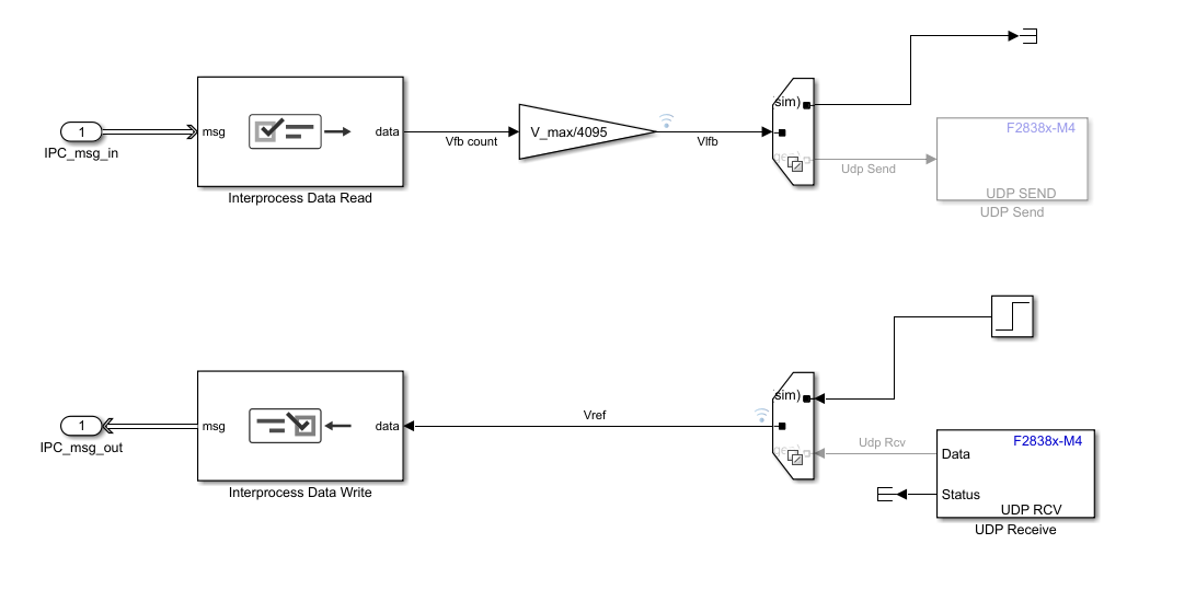
The Arm Cortex-M reference model, when configured for simulation, executes the simulation branch of the Variant Source and Variant Sink blocks. In this case, the simulation is a Step block that changes the reference voltage from 1 V to 2 V.
Run the simulation. The Simulation Data Inspector shows the simulation of the reference voltage step that the C2000 processor requests from the Arm Cortex-M processor. The results shows that the step request occurs at 0.05 sec and the output of the converter, marked Vfb on the figure, tracks the set point, marked Vref.

Deployment
The Cortex-M reference model replaces the Step and Terminator blocks with the F2838x-M4 UDP Receive and F2838x-M4 UDP Send blocks. The UDP Send block sends the output voltage over the network. The host model receives this value and displays it on graph and display panel. The UDP receives the value Vref from the host and sends it to CPU1 by using an Interprocess Data Channel block. CPU1 changes its set point upon receiving a new value.
Target Network Configuration
On the target UDP Send block, the remote IP port has to match the local IP port of the host model UDP Receive block. Make sure that the remote IP address matches the host IP address.
On the target UDP Receive block, the local IP port has to match the remote IP port of the host model UDP Send block.

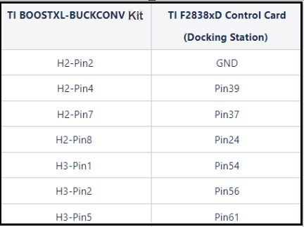
Deploy the model to the TI F2838xD (SoC) control card. Open the SoC Builder (SoC Blockset) tool. Mapping for the connection between the TI F2838xD Control Card and theTI BOOSTXL-BUCKCONV kit:
Host Configuration
A host model containing UDP Write (HOST) (SoC Blockset) and UDP Read (HOST) (SoC Blockset) blocks can send commands to and receive data from the deployed application running on the TI F2838xD (SoC) control card over the network. This figure shows a sample host model, incluing Dashboard Scope, Display, and Knob blocks for the user interface, that controls and monitors the output voltage of the DC-DC power supply. To open the host model, run the following code.
open_system("soc_dcdc_buck_host");
Further Exploration
Modify the control algorithm and daughter board to include a network-managed On-Off switch.
Extend the C2000-Arm Cortex-M model to other control systems, such a motor control.
You can also select a web site from the following list:
Americas
- América Latina (Español)
- Canada (English)
- United States (English)
Europe
- Belgium (English)
- Denmark (English)
- Deutschland (Deutsch)
- España (Español)
- Finland (English)
- France (Français)
- Ireland (English)
- Italia (Italiano)
- Luxembourg (English)
- Netherlands (English)
- Norway (English)
- Österreich (Deutsch)
- Portugal (English)
- Sweden (English)
- Switzerland
- United Kingdom (English)