Design Anti-Aliasing Filter for Analog-to-Digital Converters
R2026bThis example shows how to design an analog anti-aliasing filter that you can use with an analog-to-digital converter (ADC). In this example, the filter cut-off frequency is 500 Hz and the sampling frequency is 1000 Hz.
Open Model
Open the model.
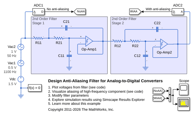
The two AC Voltage Source blocks, labeled Vac1 and Vac2, and the DC Voltage Source block, labeled Vdc, provide the test signal. This signal incorporates:
A high-frequency, 1100 Hz, sinusoid with an amplitude of 0.5 V
A low-frequency, 50 Hz, sinusoid with an amplitude of 1 V
A DC offset of 1.5 V
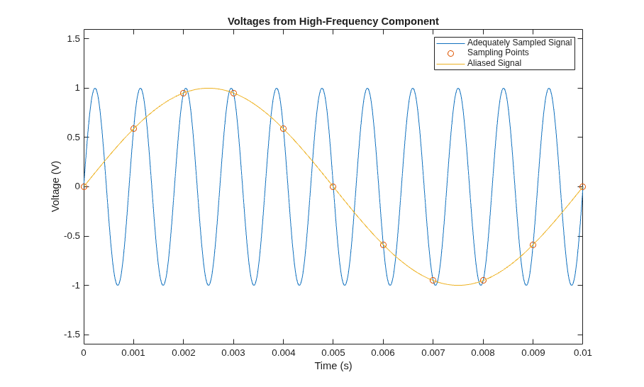
The anti-aliasing filter must preserve the DC offset and low-frequency component in the output signal. The filter must also prevent the ADC from recording the high-frequency component because the frequency of this component exceeds half the sampling frequency. Aliasing causes low-frequency components to appear in the reconstructed signal that are not present in the original signal. The alias frequency is the absolute difference between the sampling frequency and the input frequency. This plot shows aliasing of the high-frequency component of the test signal in the time domain. If you sample the 1100 Hz voltage signal at 1000 Hz, the reconstructed signal is a 100 Hz sinusoid.
The analog anti-aliasing filter attenuates high-frequency components in the analog signal before the ADC samples and converts the signal into a digital signal to remove aliased components from the output signal. The two 2nd Order Filter areas represent the two stages of the filter. Each stage uses a Band-Limited Op-Amp block, Resistor blocks, and Capacitor blocks to create a second-order lowpass filter that uses a Sallen-Key topology. Cascading two stages results in a fourth-order filter, which provides a steeper roll-off. This design uses 10,000 ohm resistors. The capacitance values give the correct transfer coefficient for a fourth-order Bessel filter. For more information about calculating the capacitances or to edit the filter parameters, at the MATLAB® Command Window enter edit AnalogAntiAliasingFilterInputParameters.
The masked subsystems ADC1 and ADC2 are identical models of an ADC. These simplified models do not include protection diodes. The models also neglect the current that the sampling switch draws. Additionally, because the microcontroller frame rate is typically much less than the frame rate of the ADC, the models neglect the conversion time.
Plot Simulation Results from Simscape Logging
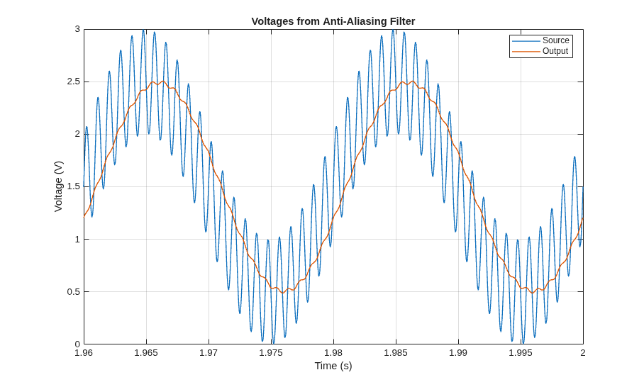
Plot the input and output voltages of the anti-aliasing filter. The output voltage closely resembles a sine wave. The 50 Hz component determines the period of 0.2 s and the amplitude of 1 V. The DC component defines the 1.5 V DC offset. The anti-aliasing filter significantly reduces the amplitude of the high-frequency component, which is prominent in the source voltage.
Plot Simulation Results from Spectrum Analyzer
To calculate the power at each frequency in the analog unfiltered signal, use the equation

where:
 is the power in watts.
 is the root-mean-square voltage in volts.
 is the resistance of the reference load in ohms.
For the DC component,

where  is the DC voltage component.
For the AC components,

where  is the amplitude of the voltage component.
For a one-ohm reference load, this calculation gives a power of 2.25 W for the DC component, 0.5 W for the 50 Hz component, and 0.125 W for the 1100 Hz component.
To convert power from watts to decibels, use the equation

where  is the power in decibels.
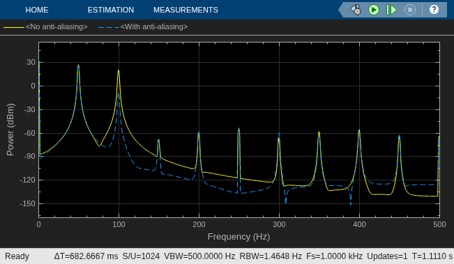
This calculation gives a power of 27.0 dBm for the DC component, 33.5 dBm for the 50 Hz component, and 21.0 dBm for the 1100 Hz component. The aim of the filter is to preserve the power at the DC and 50 Hz components and to limit the power at other frequencies.
View the power at different frequencies in the source and output signals in the Spectrum Analyzer block. With the anti-aliasing filter, the ADC correctly measures only the 50 Hz component and the DC offset. Both signals contain the expected peaks close to 33.5 dBm at 0 Hz and 27.0 dBm at 50 Hz. The source has an additional peak of 20.1 dBm at the alias frequency of 100 Hz. However, the filter reduces the power at 100 Hz to negligible levels.
See Also
Band-Limited Op-Amp | AC Voltage Source | DC Voltage Source | Resistor | Capacitor
Topics
- Fourth-Order Sallen-Key Lowpass Filter
- Low-Pass Filter Using Operational Transconductance Amplifiers
- Band-Pass Filter Using Three Mutually-Coupled Inductors
- Build and Simulate a Simple Circuit

