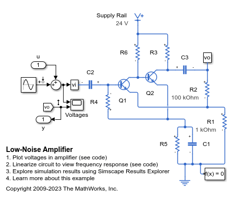
Low-Noise Amplifier
This example shows a typical low-noise audio amplifier circuit. Resistor R2 provides negative feedback to stabilize the overall amplifier gain, making it independent of transistor open-loop forward transfer gain. Circuit gain is approximately defined by (R1+R2)/R1 = 101. The simulation shows that it takes the circuit a few seconds to settle to its steady operating point, and that the output is initially clipped. Input u and output y are included to support linearization.
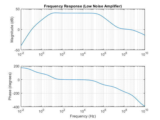
This model can be used to obtain the frequency response of the system. The Solver Configuration block option "Start simulation from steady state" should be set to ensure that the model is linearized about its nominal operating point. MATLAB® command linmod can be used to linearize the model.
If you have Simulink® Control Design™, open the model LowNoiseAmplifier. On the Apps tab, under Control Systems, click Model Linearizer. In the Model Linearizer, on the Linear Analysis tab, in the Linearize section, click Bode. The linearization points are defined by right-clicking on a Simulink line, and selecting Linearization Points.
Model
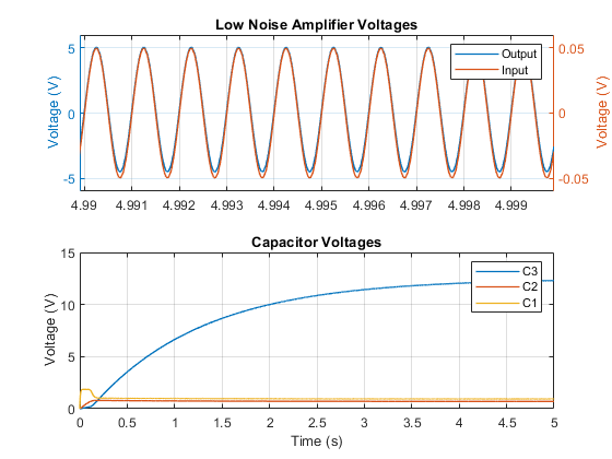
Simulation Results from Simscape Logging
This plot shows the amplifier and capacitor voltages. The gain is about 100. For visual comparison, the amplifier subplot shows only the last 10 periods of the simulation. It takes a few seconds for the circuit to settle to its steady operating point due to the charging of the capacitors, shown in the capacitor subplot.
Frequency Response