Detect and Pick Object Using KINOVA Gen3 Robot Arm with Joint Angle Control and Trajectory Control
This example shows how to deploy object detection and motion planning workflows developed in Simulink as a standalone ROS node to NVIDIA® Jetson™ compute boards. The KINOVA® Gen3 robot receives key vision sensor parameters, current robot state, and position and orientation of the object in the captured image using ROS network. The gathered data is further used to localize the object in world frame and the robot is commanded to reach the object and pick it.
This example includes two models: one specific to joint angle control and the other specific to trajectory control.
For a comparison between the two control strategies, see Joint Angle Control Versus Trajectory Control.
Required Products
MATLAB®
Simulink®
Robotics System Toolbox™
ROS Toolbox
Simulink Coder™
Stateflow®
Required Hardware
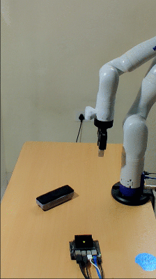
KINOVA® Gen3 Robot
One of these boards: NVIDIA Jetson Nano™, NVIDIA Jetson TX2, NVIDIA Jetson AGX Xavier™
Rectangular object (to be picked up by robot gripper)
Introduction
Robotics System Toolbox Support Package for Manipulators enables you to control manipulators using MATLAB and Simulink. The support package utilizes ROS packages provided by robot manufactures to acquire various sensor data, simulate robot models, and control the robot.
You can further utilize the standalone ROS node generation feature from the ROS Toolbox to convert robotics algorithms into a standalone ROS node. Such a node can be automatically deployed to various computer boards using Simulink. The deployment of robotics algorithms eliminates the requirement of constant communication between host PC (with MATLAB installed) and the robot. This is beneficial in many application workflows. For more information on the deployment workflow, refer to Object Detection and Motion Planning Application with Onboard Deployment.
In this example, several ROS Subscribe blocks are used to gather key robot and camera sensor parameters. These parameters along with the current joint configuration of the robot, position of the camera sensor in world frame, and the object position and orientation relative to the image, are used to localize the object in world frame. Once the object position and orientation are known in world frame, various functionalities offered by Robotics System Toolbox are used to command the robot.
This example demonstrates a workflow to design and validate complex robotics applications, which requires integration of various open-source utilities with MATLAB, and further control the robot using ROS drivers. The example has been tested with KINOVA Gen3 robot with the vision module and Robotiq 2f-85 gripper. However, the overall design of the example is modular and can be easily modified for different manipulators which can be controlled using ROS driver.
Prerequisites
If you are new to Simulink, watch the Simulink Quick Start.
Understand the algorithm to detect position and orientation, as explained in Detect Position and Orientation of a Rectangular Object Using OpenCV.
Perform the Setup and Configuration of the Jetson compute board as per instructions mentioned in Configure NVIDIA Jetson Board for Object Detection and Motion Planning.
Refer to the Design and Validate Object Detection and Motion Planning Algorithms Using Gazebo, OpenCV, and MATLAB example for more information on the object localization algorithm.
Connect to KINOVA Gen3 Robot and Initiate Required ROS Nodes to Control the Robot
Open the terminal from the catkin workspace containing ros_kortex ROS packages in the Jetson board. Execute 'source devel/setup.bash' command and the following commands in the terminal to launch required ROS nodes.
Also, replace the IP address of the robot and gripper based on the actual hardware setup. For more information on the roslaunch command, see GitHub page of KINOVA Robotics.
1. Launch the kortex_driver node.
$ roslaunch kortex_driver kortex_driver.launch ip_address:= <ipaddress> gripper:=robotiq_2f_85 start_rviz:=false start_moveit:=false
If the hardware setup and the IP address are correct, a message 'The Kortex driver has been initialized correctly!' displays on the terminal window.
2. Open new terminal window at the same folder location and execute 'source devel/setup.bash'. Launch the kortex_vision node by executing the following command.
$ roslaunch kinova_vision kinova_vision_color_only.launch device:=<ipaddress>
3. Open new terminal windows at the same folder location and execute 'source devel/setup.bash'. Launch the detect_object node by executing the following command.
$ rosrun opencv_node detect_object
This launches two image windows - One is the output of canny edge detection and the other is the original image with an overlay of a red rectangle. In an ideal setting, the red rectangle should match the boundary of the object. If the object detection is not as desired, refer to Troubleshooting Object Detection for more details.
Connect to ROS Master Running on Jetson Board from MATLAB
Configure ROS network parameter for connectivity and deployment as per setup instructions mentioned under the section Configure the Connection to the ROS Device in Generate a Standalone ROS Node from Simulink.
Note: The workspace folder must be the same in which you have downloaded the ROS packages from Kinova Robotics.
Because you already started the ROS core in the earlier step, you need not start the ROS core on the rosdevice using runCore command from MATLAB.
Model for Joint Angle Control
Open the manipdemo_DetectAndPick_Joint model.
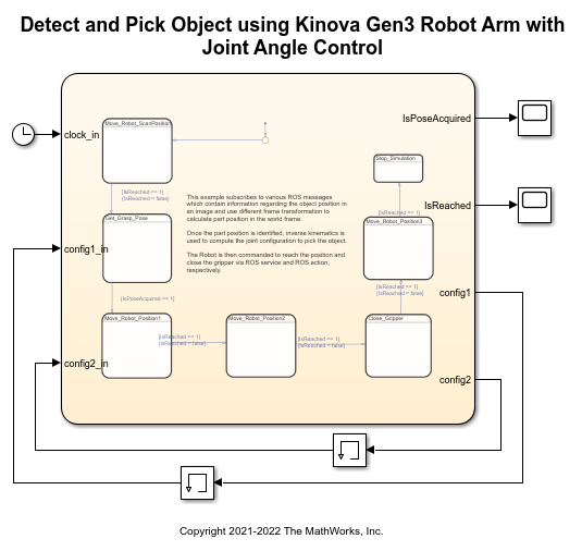
The model consists of a state machine, which performs object localization and motion planning for a robotic manipulator.
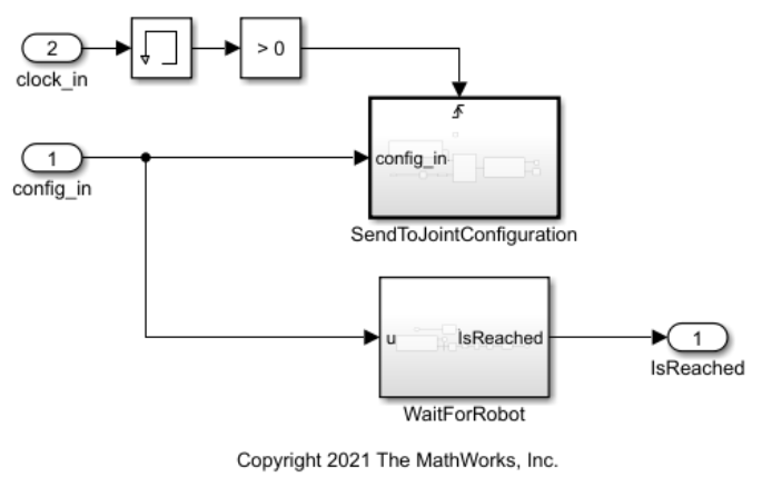
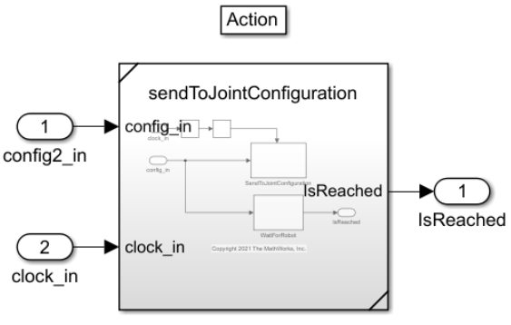
SendToJointConfiguration Subsystem
This subsystem commands the robot to move to a particular joint angle configuration. It also commands the gripper to open, and uses ROS interface for Kinova Gen3 robot. For more information refer Control Individual Joint Angle of KINOVA Gen3 Robot. It also monitors if the robot has moved to it's commanded position. If you are using a different manipulator which can be controlled by ROS driver, then modify this subsystem accordingly.
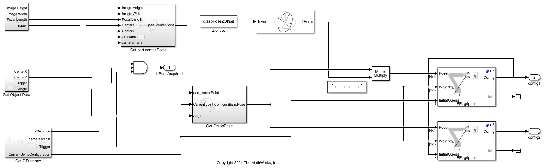
getGraspPose Subsystem
This subsystem calculates the robot joint configuration to reach the object. To compute the desired joint configuration, it uses vision sensor properties such as image height, image width and focal length; current joint configuration of the robot, and the relative position and orientation of the object. The algorithm to calculate the desired joint configuration is similar as mentioned in Design and Validate Object Detection and Motion Planning Algorithms Using Gazebo, OpenCV, and MATLAB.
Move to Position 1
Once the desired joint configuration has been calculated, robot is commanded to move to the first position. It is about 15 cm directly above the object. Because the rotation of the object is considered while calculating the desired joint configuration, the gripper should align with the orientation of the object when the robot reaches to Position 1.

Move to Position 2
Once the robot reaches to the first position, it is commanded to move to the second position. At the end of robot motion, the object should be inside the grasping region of the robot.
Close the Gripper
At this stage, the robot gripper is at the desired position to pick the object. The subsystem sends the command to close the gripper. The desired closing position and effort might change with size and material of the object.

Move back to Position 1 and Stop the simulation
Once the object is firmly picked up by the gripper, the robot is commanded to retract to first position. Once the robot motion is complete, the execution of model stops.
Modify Offsets
The image localization and path planning algorithm considers certain offsets while calculating desired grasping pose. The default values are assigned to these offsets in the preload function of the model. The description for each offset is as following:
objHeight: Height of the object
heightOffset: Offset between Robot base and the base of the object. If the object is lying on the same surface as the robot base, then the offset will be zero.
graspPoseZOffset: Z offset for first position. This will decide the height of the robot gripper from the object at first position.
graspPoseOffset: Final correction in the calculation of grasp pose. Use this offset to remove any modeling errors and to set the robot gripper height above the surface at second position.
cameraOffset: Offset between robot body and camera sensor. Fixed for Kinova Gen3 robot.
Ensure that you change these values accordingly before proceeding further. You can start with estimated values and then fine tune them by observing the robot's behavior.
Run and Verify the Model using MATLAB connectivity
In the previous step, the required ROS nodes are already launched from the Jetson board, to ensure the connection with the robot and compute board. Place the object in the field of view of the vision sensor. Click Simulate on the Simulink toolbar and then click Run. This establishes a connection between MATLAB and ROS master running on the Jetson board.
Observe the robot motion and confirm that the robot is picking the object as intended.
Run and Verify the Model Using Standalone ROS deployment
Navigate to ROS tab and click Build & Deploy. This will generate the code from the model, transfer it to specified workspace on Jetson, and build it.
You can use isNodeRunning, runNode and stopNode feature of rosdevice to interact with the deployed ROS node. Repeat the same verification steps as mentioned in the earlier section to verify the intended behavior of the autogenerated ROS node.
Model for Trajectory Control
In the previous model, the desired joint angle configuration has been sent to the robot. However, you do not have any explicit control of the intermediate trajectory between current joint configuration and the desired joint configuration. For an accurate control of the end effector position, you can control the robot by sending a pre-computed joint position, velocity, and acceleration commands.
To know more about this control strategy, open the manipdemo_DetectAndPick_Traj model.
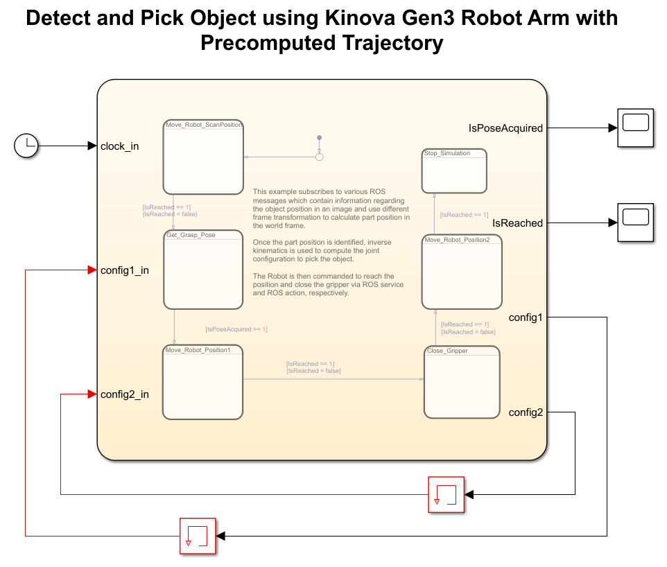
The model consists of a state machine, which performs object localization and motion planning for a robotic manipulator. The overall state machine is similar to the state machine described in the model for joint angle control. For example, the subsystem to move to position 2 looks like this:
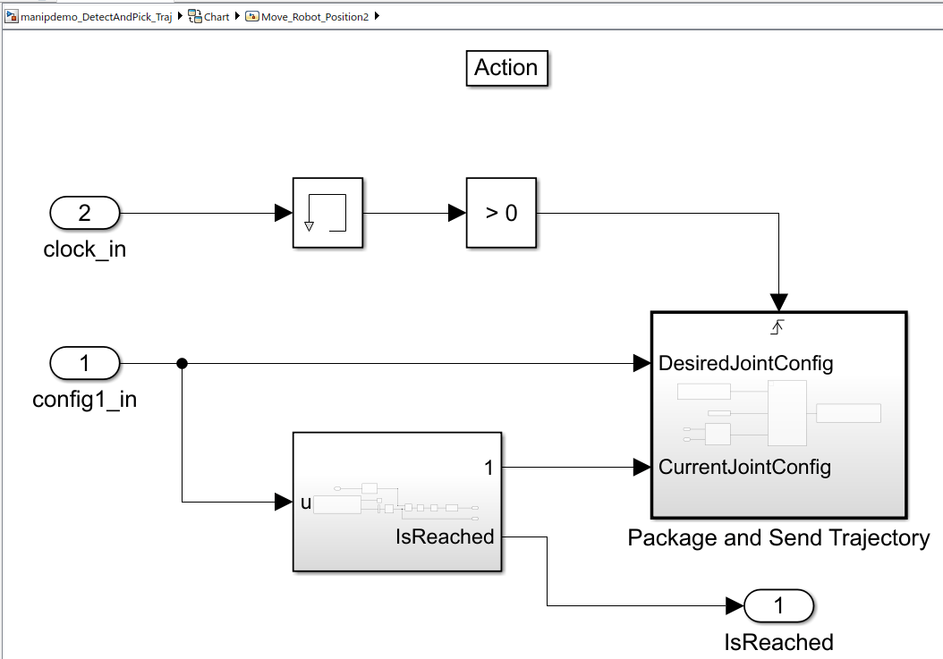
Package and Send Trajectory
The Package and Send Trajectory subsystem in Move_Robot_Position2 consists of three primary blocks related to ROS and auxiliary subsystem to calculate the joint configuration for each waypoint. The Blank ROS message block is configured to create a blank message for control_msgs/FollowJointTrajectoryActionGoal ROS action goal. The MATLAB function block, packageTrajectory calculates interpolated joint angle trajectory and assigns various values to blank message fields. Finally, the publisher block is configured for /my_gen3/gen3_joint_trajectory_controller/follow_joint_trajectory/goal ROS action and for sending commands to robot to follow the precomputed joint angle trajectory.

You can verify the entire model for trajectory control using the same steps as mentioned in Run and Verify the Model using MATLAB connectivity and Run and Verify the Model Using Standalone ROS deployment (for the manipdemo_DetectAndPick_Joint model in the previous sections).
You can also select a web site from the following list:
Americas
- América Latina (Español)
- Canada (English)
- United States (English)
Europe
- Belgium (English)
- Denmark (English)
- Deutschland (Deutsch)
- España (Español)
- Finland (English)
- France (Français)
- Ireland (English)
- Italia (Italiano)
- Luxembourg (English)
- Netherlands (English)
- Norway (English)
- Österreich (Deutsch)
- Portugal (English)
- Sweden (English)
- Switzerland
- United Kingdom (English)