Timer Capture
Add-On Required: This feature requires the Embedded Coder Support Package for STMicroelectronics STM32 Processors add-on.

Libraries:
Embedded Coder Support Package for STMicroelectronics STM32 Processors /
STM32F3xx Based Boards
Embedded Coder Support Package for STMicroelectronics STM32 Processors /
STM32F4xx Based Boards
Embedded Coder Support Package for STMicroelectronics STM32 Processors /
STM32F7xx Based Boards
Embedded Coder Support Package for STMicroelectronics STM32 Processors /
STM32G4xx Based Boards
Embedded Coder Support Package for STMicroelectronics STM32 Processors /
STM32H7xx Based Boards (Dual-core)
Embedded Coder Support Package for STMicroelectronics STM32 Processors /
STM32H7xx Based Boards (Single-core)
Embedded Coder Support Package for STMicroelectronics STM32 Processors /
STM32L4xx Based Boards
Embedded Coder Support Package for STMicroelectronics STM32 Processors /
STM32L5xx Based Boards
Embedded Coder Support Package for STMicroelectronics STM32 Processors /
STM32U5xx Based Boards
Embedded Coder Support Package for STMicroelectronics STM32 Processors /
STM32WBxx Based Boards
Description
Output the capture compare register value of the selected timer module and channel when configured in input mode.
Specify the length of data to be read from the capture compare register in
Capture data length. For data length greater than
1, DMA must be added for the selected timer module and channel in
STM32CubeMX project.
Select Output data length to output the length of read data.
Select Output status to output status of read data. Status output
1indicates overrun error.Select Output direction to output counter direction.
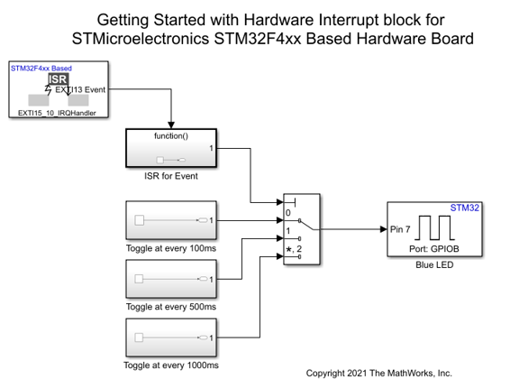
To avoid overrun error while reading capture compare register values, you can place the timer capture block within function call subsystem connected to Hardware Interrupt block with one of the following events.
Capture compare event of the selected timer and channel- If length of capture compare data to be read is equal1. This ensures block outputs data when capture compare event interrupt of the selected timer and channel occurs.Ensure that the interrupt for the capture compare event is configured in Configuration Parameters > timers > show TIM# > Configurations
Transfer complete event of the DMA configured for selected timer
                            and channel
- If length of capture compare data to be read is greater than1. This ensures block outputs data once DMA has read the specified length of data from capture compare register and transfer complete event Interrupt is generated.
Examples

Ports
Output
Parameters
Extended Capabilities
Version History
Introduced in R2022b
You can also select a web site from the following list:
Americas
- América Latina (Español)
- Canada (English)
- United States (English)
Europe
- Belgium (English)
- Denmark (English)
- Deutschland (Deutsch)
- España (Español)
- Finland (English)
- France (Français)
- Ireland (English)
- Italia (Italiano)
- Luxembourg (English)
- Netherlands (English)
- Norway (English)
- Österreich (Deutsch)
- Portugal (English)
- Sweden (English)
- Switzerland
- United Kingdom (English)