Using Hardware Interrupt Block to Create an ISR on STMicroelectronics STM32 Processor Based Boards
This example shows how to use a Hardware Interrupt block to create an interrupt service routine (ISR) in the generated code for Embedded Coder® Support Package for STMicroelectronics® STM32 Processors Based Boards.
Using this example, you can:
Create ISRs to react to the events on STM32 Processor Based hardware boards.
Configure the Hardware interrupt block to service pressing of the user button from an ISR on the NUCLEO-F429ZI board.
Introduction
The Embedded Coder Support Package for STMicroelectronics STM32 Processors enables you to use Simulink® blocks to access peripherals during run time and use the STM32CubeMX tool to configure peripherals on the processor.
In this example you will learn how to configure a Simulink model with Hardware Interrupt block to generate code and make a blue LED blink at different rates on the press of a button on the STMicroelectronics NUCLEO-F429ZI board.
Prerequisite
Complete the following tutorials:
Getting Started with STMicroelectronics STM32 Processor Based Boards
Required Hardware
To run this example you need the following hardware:
STMicroelectronics NUCLEO-F429ZI board
Micro USB cable
Model
open_system('stm32_hwi_gettingstarted');
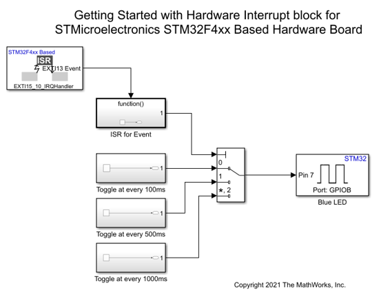
Using this model you can make a blue LED blink at different rates on the press of a button on NUCLEO-F429ZI board.
You can read the logical state of the user button at faster rate so you do not miss any changes in the user button status. To optimize the model, you can use an Hardware Interrupt block to generate an ISR which is triggered only when user button is pressed. With this rational, any status change in user button gets notified.
Configure the Hardware Interrupt Block in Simulink to Make LED Blink
In this task, you will configure the target model to make the blue LED blink at different rates in the model.
1. Open the stm32_hwi_gettingstarted target model.
2. Configure the blocks. Double-click the block to open the block parameter dialog box.
User button (blue button) is connected to pin 13 of GPIOC port (PC13) so it triggers an event EXTI 13.
The blue LED is connected to pin 7 of GPIOB port (PB7).

3. Create a new STM32CubeMX project or browse to an existing STM32CubeMX project. Launch the STM32CubeMX project in the STM32CubeMX tool. For details, see Getting Started with STMicroelectronics STM32 Processor Based Boards.
4. Configure the following configurations in your selected STM32CubeMX project to toggle user LEDs.
PB7 (Pin 7 of GPIOB) as GPIO_Output
PC13 pin as GPIO_EXTI13 to generate event EXTI 13 and to trigger corresponding ISR.

GPIO additional settings

5. In your STM32CubeMX project, ensure to perform the following configurations:
Enable Do not generate the main() under Project Manager > Project.
Disable Generate under root under Project Manager > Project.
Under Project Manager > Advanced Settings > Driver Selector, select low level (LL) drivers for the peripherals.
Under Project Manager > Advanced Settings > Generate Functions Calls, deselect Do Not Generate Function Calls for all the peripheral initialization function calls.
Under Project Manager > Advanced Settings > Generate Function Calls, deselect Visibility (Static) for all the peripheral initialization function calls.
Save the project.
Generate Code and Load on Hardware Board from Simulink Model
1. To genearte the code for the model, press Ctrl+B or click Build, Deploy & Start.

2. Follow the build process by opening the diagnostic viewer using the link provided at the bottom of the model canvas. After you load the code on the board, a blue LED blinks on the hardware board, indicating that the code is running.
Other Things to Try
Configure with different pins and run the example.
Configure at different rate and analyze the behavior.
See Also
You can also select a web site from the following list:
Americas
- América Latina (Español)
- Canada (English)
- United States (English)
Europe
- Belgium (English)
- Denmark (English)
- Deutschland (Deutsch)
- España (Español)
- Finland (English)
- France (Français)
- Ireland (English)
- Italia (Italiano)
- Luxembourg (English)
- Netherlands (English)
- Norway (English)
- Österreich (Deutsch)
- Portugal (English)
- Sweden (English)
- Switzerland
- United Kingdom (English)