Using SPI to Read and Write Data to SPI EEPROM on STM32 Processor
This example shows how to configure and use SPI blocks to read and write data using Embedded Coder® Support Package for STMicroelectronics® STM32 Processors.
In this example, you will learn how to read and write data to an external SPI EEPROM using the SPI Transmit block, the SPI Receive block, and interrupts
Required Hardware
The external EEPROM (25AA080) is an 8KB SPI bus serial interface EEPROM from Microchip. This device uses a standard SPI protocol that is common to many other EEPROMs provided by different vendors. For more details about the device, refer to the 25AA080 data sheet.
Hardware Connections
The SPI EEPROM uses the following 8-bit opcodes for enable, write data, read data, and read status.
       Command  | Opcode | Operation
    _ _ _ _ _ _ _ _ _ _ _ _ _ _ _ _ _ _ _ _ _ _ _ _
        WREN    | 6      | Enable Write Operations
        WRITE   | 2      | Write Data to Memory
        READ    | 3      | Read Data from Memory
        RDSR    | 5      | Read Status Register
    _ _ _ _ _ _ _ _ _ _ _ _ _ _ _ _ _ _ _ _ _ _ _ _
The hardware connections made are dependent on the EEPROM usage. The SPI connection in this example are made between Nucleo H7 board and SPI EEPROM chip EEPROM (25AA080) is an 8KB SPI EEPROM Memory as listed.
     SPI EEPROM pin |  STM32H7
 _ _ _ _ _ _ _ _ _ _ _ _ _ _ _ _ _
      /CS   (pin 1) |  SPISTE
      SO    (pin 2) |  SPIMISO
      /WP   (pin 3) |  3.3 V
      VSS   (pin 4) |  GND
      SI    (pin 5) |  SPIMOSI
      SCK   (pin 6) |  SPICLK
      /HOLD (pin 7) |  3.3 V
      VCC   (pin 8) |  3.3 V
 _ _ _ _ _ _ _ _ _ _ _ _ _ _ _ _ _
Available Models
You can use the open_system command to open the Simulink® models. For example, use this command for a STM32 Processor based hardware board:
open_system('stm32_spi_eeprom_interrupt.slx');

Read and Write Data to SPI EEPROM Using the SPI Transmit Block, the SPI Receive Block, and Interrupts
The model writes data values of various types to EEPROM and reads back data from the corresponding EEPROM address to show successful communication. This model can be used only for hardware boards with an SPI FIFO length of 15.
SPI blocks are configured with the Data bits parameter set to 8 to send the 8-bit opcodes and write/read the 8-bit data. Set the Hardware NSS signal to disabled provided by the SPI peripheral in STM32CubeMX configuration parameters under SPI module, to ensure the slave is not deselected between data transfers.
In this case, the Explicit GPIO calls option is used to set Chip select (provided by SPI module) assignment to GPIOA to ensure that the peripheral is selected continuously for multiple data transfers. The receive FIFO is configured to trigger the interrupt for a FIFO length of 15.
The model consists of Write EEPROM Data, Transmit Read Command, Read EEPROM Data, and Data Realignment subsystems along with Display blocks. Write and read data operations are triggered alternatively using the STATVAR variable.
The Write EEPROM Data subsystem performs the EEPROM write enable operation using SPI Transmit and SPI Receive blocks. Before every write cycle, block priorities are set to ensure that SPI Transmit is executed first. The input data of different types are packed in 8-bit packets using the Byte Pack block and converted to uint16. Data is then written to the EEPROM at the address location 0x0020 using the SPI Transmit block. After this, the program waits until the receive interrupt is triggered. When the receive interrupt is triggered, the data from the receive FIFO is read and discarded.
The Transmit Read Command subsystem is then triggered, which sends a read command and an address with dummy data of the size of the data to be read. After this, the program waits until the receive interrupt is triggered. When the receive interrupt is triggered, data from the receive FIFO is read.
The Data Realignment subsystem performs byte reordering to create 8-bit word packets, which are unpacked to data of required type using the Byte Unpack block. This data is then shown using display blocks.
Run the model
1. Open the stm32_spi_eeprom_interrupt model. This model is configured for the STM32 H7xx Based (Single core) board. To configure the model to run on other STM32 based board, change the Hardware board parameter in the Configuration Parameters > Hardware Implementation pane.
2. Launch STM32 CubeMX project and navigate to Pinout and Configuration > connectivity > SPI module.

3. Enter the value for Desired baud rate in bits/sec as 500, and set HardwareNSS to Disable.
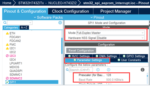
4. Set FIFO thershold to FIFO thershold 15 data.

5. In the Configuration Parameters window, click Hardware Implementation and navigate to Target hardware resources > External mode and set Communication interface to Serial port.
6. Navigate to Connectivity and specify the Serial COM port.
Note: To see the list of available COM ports on your computer, select Start > Control Panel > Device Manager > Ports (COM &LPT).

7. Open Hardware tab and click Monitor & Tune. Observe the output data using Display blocks.
8. Change the input data values and observe the changes.
More About
You can also select a web site from the following list:
Americas
- América Latina (Español)
- Canada (English)
- United States (English)
Europe
- Belgium (English)
- Denmark (English)
- Deutschland (Deutsch)
- España (Español)
- Finland (English)
- France (Français)
- Ireland (English)
- Italia (Italiano)
- Luxembourg (English)
- Netherlands (English)
- Norway (English)
- Österreich (Deutsch)
- Portugal (English)
- Sweden (English)
- Switzerland
- United Kingdom (English)