ADC Interface
Convert analog signal on ADC input pin to digital signal
Libraries:
SoC Blockset /
Peripherals
C2000 Microcontroller Blockset /
Test Bench Blocks
Embedded Coder Support Package for Infineon AURIX TC3x Microcontrollers /
Test Bench Blocks
Embedded Coder Support Package for Infineon AURIX TC4x Microcontrollers /
Test Bench Blocks
Description
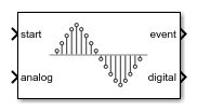
The ADC Interface block simulates the analog-to-digital conversion (ADC) of a hardware board. The input analog signal gets sampled and converted into a representative digital value. A start event message signals the block to sample the input analog voltage signal. When the conversion completes, the block emits the digital representation of the analog signal and sends an event to a Task Manager block. At this point, a connected task can execute with the new ADC sample.
Examples
Integrate MCU Scheduling and Peripherals in Motor Control Application
Identify and resolve issues with respect to peripheral settings and task scheduling early during development.
Ports
Input
Specify an event signal to start the sampling and measurement of the analog input port signal.
Data Types: rteEvent
Input analog voltage signal to convert into a digital measurement.
Data Types: double
| single
Output
This port sends the ADC Interface input signal data as a message to the msg input port of the ADC Read block.
Data Types: SoCData
This port sends a message at whenever the analog voltage signal exceeds the specified Lower threshold and Upper threshold property values. This output connects to the input of the Task Manager block to execute the associated event-driven task to react to the over- or under-voltage input event.
Dependencies
To enable this port, enable the Enable analog watchdog parameter.
Data Types: rteEvent
This port sends a message at each analog to digital signal conversion event. This output connects to the input of the Task Manager block to execute the associated event-driven task after executing the ADC event.
Dependencies
To enable this port, enable the Enable interrupt parameter.
Data Types: rteEvent
Parameters
Single Channel
An input analog signal can be represented in digital values in the form of 12 or 16 bits. The minimum value of an analog signal that can be represented in 1 bit is called resolution. One bit represents the minimum voltage resolution measurable by the ADC. The minimum voltage resolution can be determined using the following equation:
where n
is the Resolution
(bits) and Vref
is the Voltage reference
(V) parameter values.
Example: 16
The reference voltage determines the total voltage range that the ADC can convert into a digital value without saturating. Any voltage signal higher than this value produces the maximum possible value that can represented by the Resolution (bits) parameter.
Example: 3.3
Specify the time required for the ADC to capture the input voltage during sampling.
Example: 200e-9
Specify the required time to convert the physical voltage sample to the digital representation and output the value.
Example: 20e-9
Specify the charge or discharge time constant of the ADC sample acquisition circuitry.
Multichannel
Specify the number of channels used by the ADC module. Specifying 2 or more channels allows for either more efficient or precise measurements of the input signal.
Select the type of multichannel conversion.
Sequential
— Take sequential measurements on each ADC channel. At a new ADC event, the next channel in the sequence of channels takes a new measurement of the input signal. All other previous channel values remain unchanged. Sequential measurement improves sampling by allowing for individual conversion times of each channel to exceed the sample rate of the ADC module.Simultaneous
— Take simultaneous measurements on each ADC channel. At a new ADC event, all channels take a new measurement of the input signal, replacing the previously captured value. Simultaneous measurement allows for noise to be removed from the measurement using an average value or other filter.Oversampling
— Take oversampled measurements across the channels of the ADC. Between two timer-driven ADC events, each channel takes a time offset ADC measurement, resulting in the channels sampling the input signal evenly between the two ADC events. The resulting channel output provides an oversampled measurement of the input signal at each sample. Oversampling measurement allows for the ADC module to exceed the theoretical Nyquist sample rate of the individual channel and ADC hardware.
Event
Select this parameter for the ADC Interface block to generate an interrupt following an ADC acquisition and to enable the event output port. You can connect this event port to a Task Manager block to simulate asynchronous ADC operation.
Select the timing condition for when to generate the ADC interrupt event. Using
Acquisition + Conversion time
, the interrupt is generated
when the complete measurement is available. Using Acquisition
time
, the interrupt is generated prior to the measurements
availability. Allowing for the associated task to start during the conversion and
reduce execution delay in the total measurement cycle.
Select this parameter for the ADC Interface block to generate an analog watchdog interrupt following an ADC acquisition where the input voltage exceeds the specified Lower threshold and Upper threshold parameter values. Selecting this parameter also enables the wd event output port, which you can connect to a Task Manager block to simulate task action on an over-or under-voltage event on the ADC input signal.
Specify the lower threshold value of the analog input signal on which to trigger an analog watchdog interrupt event.
Example: 0.2
Specify the upper threshold value of the analog input signal on which to trigger an analog watchdog interrupt event.
Example: 3.0
Specify the time required by the ADC hardware module from the completion of the conversion to the generation of the interrupt in software.
Example: 0.00001
Extended Capabilities
To automatically generate C code for your design, and execute on an SoC device, use the SoC Builder (SoC Blockset) tool. To generate and execute C code for your SoC models, Embedded Coder® features are required. For more information on generating code for SoC designs, see Use SoC Builder to Generate SoC Design (SoC Blockset).
Version History
Introduced in R2020b
MATLAB Command
You clicked a link that corresponds to this MATLAB command:
Run the command by entering it in the MATLAB Command Window. Web browsers do not support MATLAB commands.
Sélectionner un site web
Choisissez un site web pour accéder au contenu traduit dans votre langue (lorsqu'il est disponible) et voir les événements et les offres locales. D’après votre position, nous vous recommandons de sélectionner la région suivante : .
Vous pouvez également sélectionner un site web dans la liste suivante :
Comment optimiser les performances du site
Pour optimiser les performances du site, sélectionnez la région Chine (en chinois ou en anglais). Les sites de MathWorks pour les autres pays ne sont pas optimisés pour les visites provenant de votre région.
Amériques
- América Latina (Español)
- Canada (English)
- United States (English)
Europe
- Belgium (English)
- Denmark (English)
- Deutschland (Deutsch)
- España (Español)
- Finland (English)
- France (Français)
- Ireland (English)
- Italia (Italiano)
- Luxembourg (English)
- Netherlands (English)
- Norway (English)
- Österreich (Deutsch)
- Portugal (English)
- Sweden (English)
- Switzerland
- United Kingdom (English)