Get Started with Multicore External Mode on TI F2838x
R2026bThis example shows how to use multicore external mode on TI™ F2838x processors. Configure the CM4 core as an XCP communication gateway and monitor signals and tune parameters on CPU1 and CPU2 simultaneously through a single Ethernet connection.
The TI TMS320F28388D processor contains three processing cores:
CM4 (ARM® Cortex®-M4)
CPU1 (C28x DSP)
CPU2 (C28x DSP)
The CM4 core receives XCP packets from the host computer over Ethernet and routes them to CPU1 and CPU2 through the on-chip IPC bus. The CM4 core also supports its own signal monitoring and parameter tuning. Because the gateway handles communication for all cores, CPU1 and CPU2 do not require separate host communication connections.
Required Products
In addition to the products listed in the This example uses section, this example requires:
TI Code Composer Studio (CCS) v12+
TI C2000 Code Generation Tools (CGT v22.6+)
Supported Hardware
You can run this example on either of these hardware boards:
TI F2838x ControlCARD with 180-pin Docking Station.
LAUNCHXL-F28388D LaunchPad.
Communication Architecture
Multicore external mode uses the CM4 core as an XCP communication gateway between the host computer and the C28x cores. The host computer communicates with the CM4 core over TCP/IP Ethernet. The CM4 core forwards communication packets to CPU1 and CPU2 through IPC channels. The CM4 core also manages its own XCP session for signal monitoring and parameter tuning.
The default communication configuration uses these TCP ports:
CM4 — Port
17725CPU1 — Port
17726CPU2 — Port
17727
The default IPC channel configuration is:
CM4 and CPU1 — IPC channels
0and1CM4 and CPU2 — IPC channels
2and3
For successful multicore external mode operation:
Build the CM4 model before you build the CPU1 and CPU2 models.
Start external mode on the CM4 model before you start external mode on CPU1 or CPU2.
Use unique TCP ports for each core.
Use matching IPC channel pairs between the CM4 gateway model and the C28x models.
IPC Channel Mapping
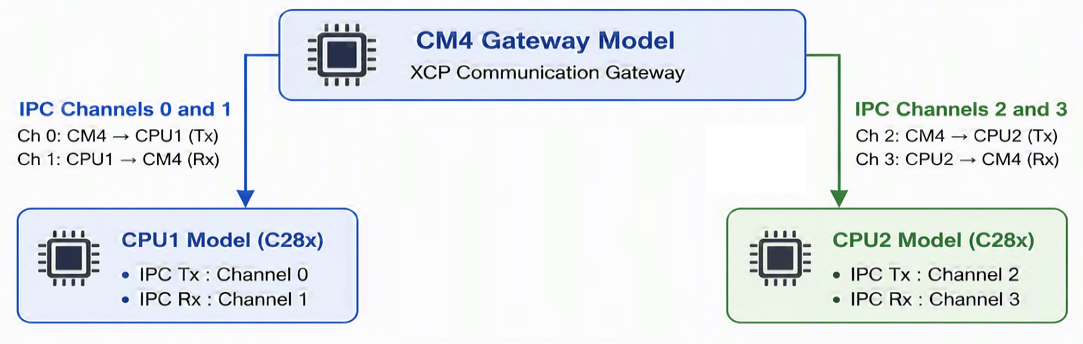
The RX and TX IPC channel values in each C28x model must match the corresponding RX and TX IPC channel values configured in the CM4 gateway model. CPU1 and CPU2 must use unique IPC channel pairs.
Multicore External Mode Workflow
Use the following workflow to build, deploy, and connect multicore external mode applications.
Model Names Used in This Example
Core | Model |
CM4 |
|
CPU1 |
|
CPU2 |
|
These model names are referenced throughout the example.
Workflow
The multicore external mode workflow follows three phases:
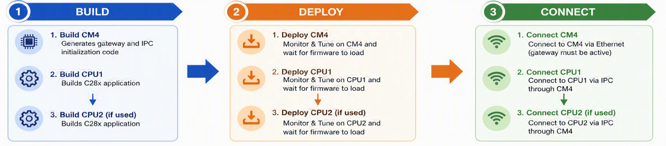
Note: Perform each phase in the order CM4 → CPU1 → CPU2. The CM4 gateway must be active before CPU1 and CPU2 can communicate with the host computer.
BUILD Phase:
slbuild(CM4)- generates gateway + IPC init codeslbuild(CPU1)- builds C28x applicationslbuild(CPU2)- builds C28x application (if used)
DEPLOY Phase:
Monitor & Tune on CM4 -> wait for firmware to load
Monitor & Tune on CPU1 -> wait for firmware to load
Monitor & Tune on CPU2 -> wait for firmware to load (if used)
CONNECT Phase:
CM4 connects first (gateway must be active)
CPU1 connects via IPC through CM4
CPU2 connects via IPC through CM4 (if used)
Overview of the Simulink Models
This example uses three pre-configured models, one for each core:
c2838xMulticoreExtmodeCm4
modelName = "c2838xMulticoreExtmodeCm4";
open_system(modelName)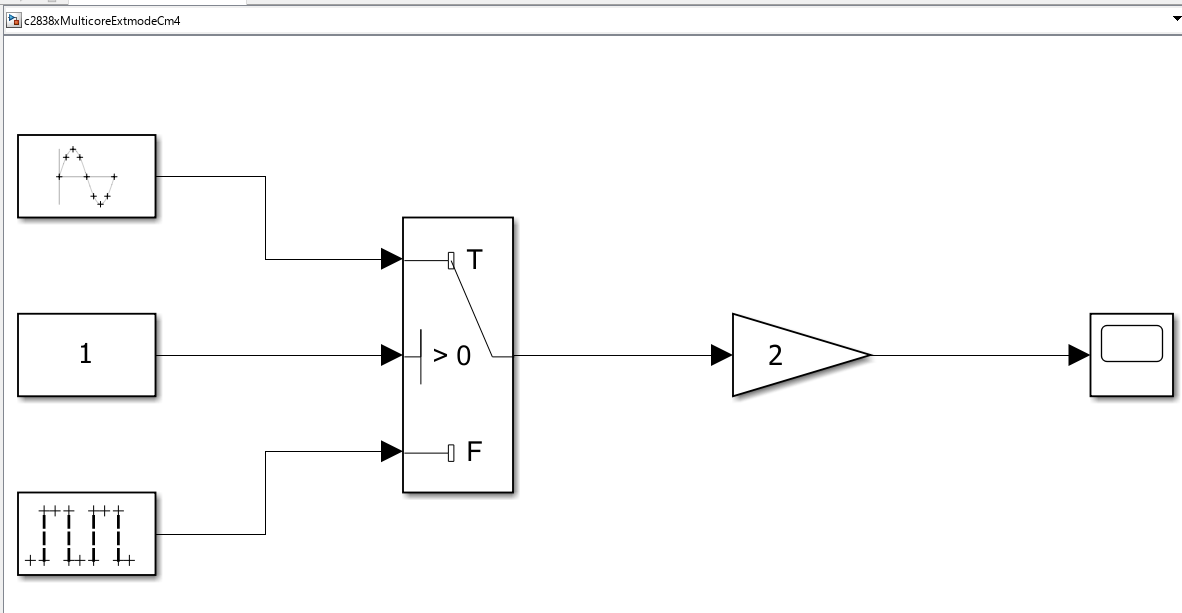
This model demonstrates signal selection and processing on the Cortex-M4 core. The model contains:
A Sine Wave source
A Pulse Generator source
A Constant block used as the switch control signal
A Switch block that selects one of the input signals
A Gain block with gain value
2A Scope block for signal monitoring
The selected signal passes through the Gain block and is streamed to the host computer through external mode.
c2838xMulticoreExtmodeCpu1
modelName = "c2838xMulticoreExtmodeCpu1";
open_system(modelName)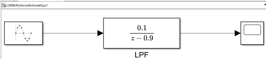
This model demonstrates signal processing on the first C28x core.
The model contains:
A Sine Wave source
A discrete low-pass filter labeled LPF
A Scope block
The low-pass filter uses the transfer function:
0.1
-------
z - 0.9
Use external mode to monitor the filtered signal and tune filter parameters during execution.
c2838xMulticoreExtmodeCpu2
modelName = "c2838xMulticoreExtmodeCpu2";
open_system(modelName)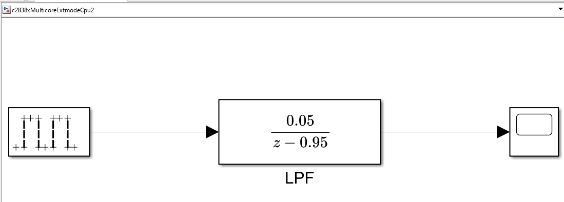
The CPU2 model demonstrates signal processing on the second C28x core.
The model contains:
A Pulse Generator source
A discrete low-pass filter labeled LPF
A Scope block
The low-pass filter uses the transfer function:
0.05
--------
z - 0.95
The scope output can be monitored independently from CPU1 and CM4.
Model Configuration
The models are pre-configured for multicore external mode.
Setting | CM4 | CPU1 | CPU2 |
|---|---|---|---|
Hardware board | TI F2838x | TI F2838x | TI F2838x |
Processing unit | CortexM4 | c28xCPU1 | c28xCPU2 |
External Mode transport | XCP on TCP/IP | XCP on TCP/IP with IPC forwarding | XCP on TCP/IP with IPC forwarding |
XCP communication gateway | Enabled | Not applicable | Not applicable |
TCP port | 17725 | 17726 | 17727 |
IPC channels | 0 and 1 for CPU1, 2 and 3 for CPU2 | 0 and 1 | 2 and 3 |
Boot from flash | Enabled | Enabled | Enabled |
Ethernet IP address | 192.168.0.12 | Not applicable | Not applicable |
Model Architecture
All three models follow the same pattern: a signal source feeds through a processing block into a Scope for monitoring.
Each uses a different waveform so you can identify the core in the Simulation Data Inspector:
CM4: Sine Wave (1 Hz) -> Switch -> Gain (2) -> Scope
CPU1: Sine Wave -> Discrete LPF (0.1/(z-0.9)) -> Scope
CPU2: Pulse Generator -> Discrete LPF (0.05/(z-0.95)) -> Scope
CM4 Model - XCP Communication Gateway with signal conditioning:
CPU1 Model - C28x DSP application with low-pass filter:
CPU2 Model - C28x DSP application with low-pass filter:
Configure the Network Connection
Connect the target hardware to the host computer by using an ethernet cable. The CM4 model uses the static IP address 192.168.0.12 by default. Configure the host computer and target hardware to use the same subnet.
Note: The host computer and the CM4 gateway must be on the same subnet. Otherwise, the host cannot reach the CM4 TCP ports, and external mode cannot connect.
To configure the network:
Set the host computer Ethernet adapter to a static IP address in the same subnet as the target (for example,
192.168.0.5with subnet mask255.255.255.0).Verify connectivity by pinging the target IP address from the host computer:
ping 192.168.0.12
To change the IP address of the target hardware:
Open the
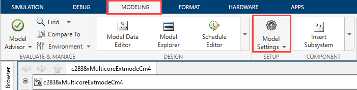
c2838xMulticoreExtmodeCm4model.In the Simulink Toolstrip, on the Modeling tab, click Model Settings.
3. In the Configuration Parameters dialog box, navigate to Hardware Implementation > Target hardware resources, select Ethernet.
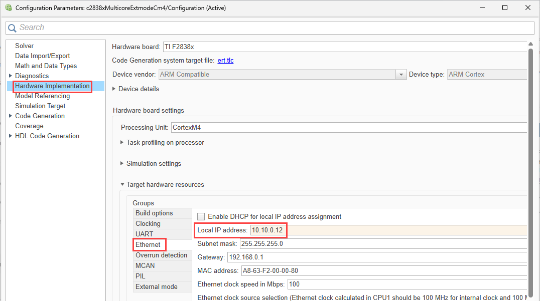
4. Set the IP address for your network.
For example, if the host computer IP address is 10.10.0.5, set the target hardware IP address to an address in the same subnet, such as 10.10.0.12.
5. Verify that the subnet mask matches the host computer's subnet mask.
Optional: Change IPC Channels or TCP Ports
The models use default IPC channels and TCP ports. Change these settings only if your application requires different channel or port assignments.
To change IPC channels or TCP ports:
Open the model.
In the Simulink Toolstrip, on the Modeling tab, click Model Settings.
In the Configuration Parameters dialog box, navigate to Hardware Implementation > Target hardware resources > External mode.
Select Specify IPC channel and TCP port numbers.
Update the IPC channel or TCP port settings.
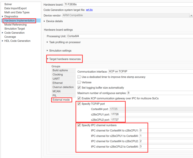
When you change these settings, follow these requirements:
The IPC channel settings in each C28x model must match the corresponding CM4 gateway settings.
CPU1 and CPU2 must use different IPC channel pairs.
IPC channel values must be in the range
0-7.Each core must use a unique TCP port.
TCP ports must be in the valid range
1024through65535.
Validate Configuration
Before you build and run the models, validate the multicore external mode configuration.
This example includes the helper script: helperValidateMulticoreExtMode.m
The helper script validates the multicore external mode configuration and reports any issues that might prevent successful communication between the CM4 gateway and the C28x cores.
The validation checks:
XCP Communication Gateway is enabled on the CM4 core.
The C28x transport layer is configured as XCP on TCP/IP with IPC forwarding.
IPC channel assignments match between the CM4 gateway and each C28x core.
IPC transmit (TX) and receive (RX) channels are different on each core.
IPC channel values are in the valid range 0–7.
IPC channel assignments do not overlap between CPU1 and CPU2.
TCP port numbers are unique across all cores.
TCP port numbers are in the valid range 1024–65535.
Manually configured C28x TCP ports match the corresponding CM4 gateway TCP ports.
No TCP Send or TCP Receive block uses a TCP port reserved by the gateway.
To validate the CM4 and CPU1 configuration, run this command:
helperValidateMulticoreExtMode( ...
    'c2838xMulticoreExtmodeCm4', ...
    'c2838xMulticoreExtmodeCpu1');
To validate the CM4, CPU1, and CPU2 configuration, run this command:
helperValidateMulticoreExtMode( ...
    'c2838xMulticoreExtmodeCm4', ...
    'c2838xMulticoreExtmodeCpu1', ...
    'c2838xMulticoreExtmodeCpu2')
The helper validates that:
IPC TX and RX channels are different for each model.
IPC channel values are in the valid range 0 through 7.
CPU1 and CPU2 do not use overlapping IPC channels.
CM4 gateway ports are unique.
TCP ports are in the valid range 1024 through 65535.
Manually configured C28x ports match the corresponding CM4 gateway ports.
TCP Send and TCP Receive blocks in the CM4 model do not use gateway-reserved ports.
Ensure that all checks return [PASS] before you continue. If any check returns [FAIL], update the reported setting and run the validation helper again.
Monitor and Tune Signals on CM4 and CPU1
In this task, you use multicore external mode with the CM4 gateway and CPU1. You build both models, start external mode on the CM4 model first, and then monitor and tune signals from CPU1 through the CM4 gateway.
Build the models
Open the c2838xMulticoreExtmodeCm4 model.
Build the model by clicking Build Model (Ctrl+B) on the Simulation tab. This action generates code and builds the model using the current configuration settings.
Alternatively, build the model programmatically by running the following command in the MATLAB Command Window:
slbuild('c2838xMulticoreExtmodeCm4');
Similarly build the c2838xMulticoreExtmodeCpu1 model.
slbuild('c2838xMulticoreExtmodeCpu1');
Deploy and Connect
Start external mode on the CM4 model.
In the c2838xMulticoreExtmodeCm4 model, from the Hardware tab, click Monitor & Tune.
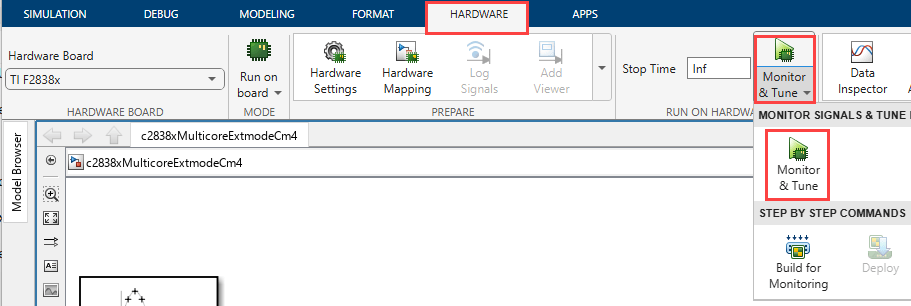
2. Wait until the model status shows that the application is running.
Start external mode on the CPU1 model.
In the
c2838xMulticoreExtmodeCpu1model, from the Hardware tab, click Monitor & Tune.Wait until the model status shows that the application is running.
Note: Start external mode on the CM4 model first. The CM4 gateway must be active before CPU1 and CPU2 can establish external mMode communication with the host computer through IPC.
Monitor Signals

Open the Simulation Data Inspector and verify that signal data streams from both cores.
Observe the following signal characteristics:
CM4 — Smooth 1 Hz sine wave with an amplitude range of -100 to +100.
CPU1 — 5 Hz square wave that toggles between 0 and 150.
Successful monitoring of both waveforms confirms communication between the host computer, the CM4 gateway, and CPU1. You should see two distinct waveforms:
Tune Parameters
While external mode is running, tune the gain parameter in the CPU1 model and observe the effect on the CPU1 waveform in the Simulation Data Inspector.
Tune CPU1 gain:
Increase the gain value from 150 to 300:
set_param([c2838xMulticoreExtmodeCpu1 '/Gain'], 'Gain', '300');
Observe that the amplitude of the CPU1 waveform increases immediately without rebuilding or redeploying the model.
Tune CM4 gain:
Change the CM4 gain from 2 to 5:
set_param('c2838xMulticoreExtmodeCm4/Gain', 'Gain', '5');
Observe that the CM4 waveform amplitude changes while CPU1 remains unaffected. Each parameter change affects only the core where the block resides.
Restore the default gain value:
set_param([c2838xMulticoreExtmodeCpu1 '/Gain'], 'Gain', '150');
set_param('c2838xMulticoreExtmodeCm4/Gain', 'Gain', '2');
The waveforms return to their original amplitudes. This behavior confirms successful independent parameter tuning on the CM4 and CPU1 cores using multicore external mode.
Monitor and Tune Signals on CM4, CPU1, and CPU2
This task extends the workflow to all three processor cores. You build and run the CM4, CPU1, and CPU2 models and monitor signals from all cores simultaneously over a single Ethernet connection..
Build the models in the order CM4 → CPU1 → CPU2:
Open the c2838xMulticoreExtmodeCm4 model.
Build the model by clicking Build Model (Ctrl+B) on the Simulation tab. This action generates code and builds the model using the current configuration settings.
Repeat the build process for the
c2838xMulticoreExtmodeCpu1andc2838xMulticoreExtmodeCpu2models.
Alternatively, build all three models programmatically by running:
slbuild('c2838xMulticoreExtmodeCm4');
slbuild('c2838xMulticoreExtmodeCpu1');
slbuild('c2838xMulticoreExtmodeCpu2');
Deploy and Connect
In the c2838xMulticoreExtmodeCm4 model, from the Hardware tab, click Monitor & Tune.
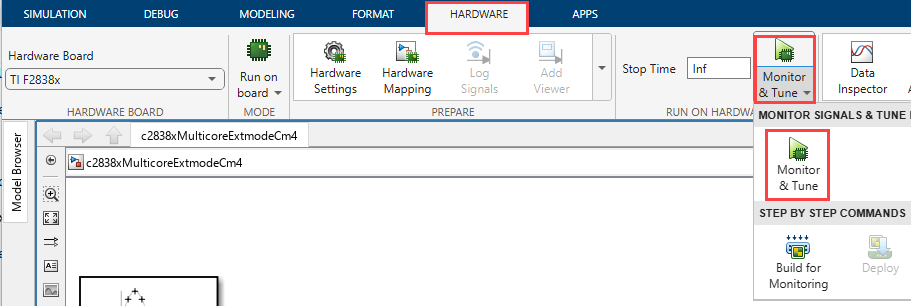
2. Wait until the model status shows that the application is running.
Similarly start external mode on the c2838xMulticoreExtmodeCpu1 and c2838xMulticoreExtmodeCpu2 models.
Note: Start external mode on the CM4 model first. The CM4 gateway must be active before CPU1 and CPU2 can exchange external mode communication with the host computer through IPC.
Monitor Signals

Open the Simulation Data Inspector and verify that signal data streams from all three cores.
Observe the following signal characteristics:
CM4 — Smooth 1 Hz sine wave with an amplitude range of -100 to +100.
CPU1 — 5 Hz square wave that toggles between 0 and 150.
CPU2 — 3 Hz sine wave with an amplitude range of -200 to +200.
Successful monitoring of all three waveforms confirms communication between the host computer, the CM4 gateway, CPU1, and CPU2 through a single Ethernet connection.
Tune Parameters
While external mode is running, tune parameters in any of the models and observe the corresponding signal updates in the Simulation Data Inspector.
Parameter change affects only the model running on the selected core.
Tune CPU1 gain:
Increase the gain value in the CPU1 model:
set_param([c2838xMulticoreExtmodeCpu1 '/Gain'], 'Gain', '300');
Tune CM4 gain:
set_param('c2838xMulticoreExtmodeCm4/Gain', 'Gain', '5');
Tune CPU2 gain:
set_param([c2838xMulticoreExtmodeCpu2 '/Gain'], 'Gain', '50');
Observe that each change affects only the waveform associated with the selected core:
Changing the CPU1 gain affects only the CPU1 waveform.
Changing the CM4 gain affects only the CM4 waveform.
Changing the CPU2 gain affects only the CPU2 waveform.
This behavior confirms independent parameter tuning on each processor core through multicore external mode. To restore the original behavior, reset the tuned parameters to their default values.
set_param([c2838xMulticoreExtmodeCpu1 '/Gain'], 'Gain', '150');
set_param('c2838xMulticoreExtmodeCm4/Gain', 'Gain', '2');
set_param([c2838xMulticoreExtmodeCpu2 '/Gain'], 'Gain', '200')
Disconnect and Stop
When you finish monitoring and tuning, disconnect the models in reverse order CPU2 → CPU1 → CM4:
Stop external mode on the
c2838xMulticoreExtmodeCpu2model by clicking Stop on the Hardware tab.Stop external mode on the
c2838xMulticoreExtmodeCpu1model by clicking Stop on the Hardware tab.Stop external mode on the
c2838xMulticoreExtmodeCm4model by clicking Stop on the Hardware tab.
Note: Stop the C28x models (CPU1 and CPU2) before stopping the CM4 model. The CM4 gateway manages the TCP connection between the host computer and the C28x cores. If the CM4 model stops first, the host loses communication with the gateway, which can cause connection errors on the CPU1 and CPU2 models.
Other Things To Try
Change the IPC channel assignments and verify the updated configuration by using the
helperValidateMulticoreExtMode.mscript.Configure custom TCP ports for the CM4, CPU1, and CPU2 models and verify successful multicore external mode communication.
Modify the CM4 Switch block control signal and observe how the output waveform changes in the Simulation Data Inspector.
Add additional signal sources or processing blocks to any model and monitor them through external mode.
See Also
Multicore External Mode on TI F2838x | Troubleshooting Multicore External Mode

