GPS HDL Acquisition and Tracking Using C/A Code
This example shows how to acquire and track multiple global positioning system (GPS) satellite signals from a GPS baseband waveform using Simulink® blocks that are optimized for HDL code generation and hardware implementation. You use the L1 Coarse/Acquisition (C/A) code in the input waveform to perform signal acquisition and track the satellites. In acquisition, you detect the satellite signals in the waveform and estimate the coarse Doppler and C/A code phase offsets for the detected satellites. In tracking, you fine-tune the estimates and correct them to recover the legacy navigation (LNAV) symbols. You can use the LNAV symbols for GPS position estimation.
Model Overview
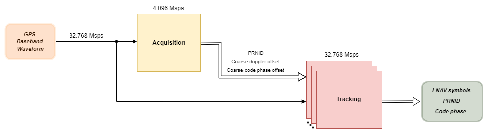
The model that you use in this example mainly consists of acquisition and tracking modules. The input to the model is a GPS baseband waveform with a sample rate of 32.768 Msps. This baseband waveform contains multiple satellite waveforms with Doppler offsets, code phase offsets, and additive white Gaussian noise (AWGN) noise in it. The model upsamples the GPS waveform by a factor of six. This increases the clock from 32.768 MHz to 196.6 MHz to achieve faster acquisition. The model supports sample rates 8.192 Msps, 16.384 Msps, and 32.768 Msps. The example is explained with the sample rate of 32.768 Msps.
The Acquisition block decimates the GPS waveform from 32.768 Msps to 4.096 Msps and operates at this sampling rate. The acquisition block detects the satellites and generates coarse estimates for them. You can search specified pseudorandom noise identification numbers (PRNIDs) in the received waveform, instead of searching all the 32 PRNIDs.
The Tracking block uses the GPS waveform at 32.768 Msps, the PRNID of the detected satellites, and the coarse estimates to track the satellites. At least four satellites are required for GPS position estimation, so tracking does not start until the acquisition process detects four satellites. The Tracking block contains eight instances of tracking logic to simultaneously track eight satellites. The Tracking block uses phase-locked loop, frequency-locked loop, and delay-locked loop to recover the pi/2-BPSK modulated LNAV symbols of each detected satellite. This figure shows an overview of the example model.
File Structure
This example uses one Simulink model, two functions, and two scripts.
gpshdlAcquisitionTracking— Model to acquire signals and track satellites.gpshdlAcquisitionAndTrackingUsingCACodeInit— Generates all the parameters and inputs required to run thegpshdlAcquisitionTrackingmodel. The model calls this script in theInitFcncallback.gpshdlAcquisitionAndTrackingUsingCACodeParameters— Generates the parameters required to run the model. The model calls this function in thegpshdlAcquisitionAndTrackingUsingCACodeInitscript.gpshdlGenerateRxInput— Generates the input GPS waveform for the receiver. The model calls this function in thegpshdlAcquisitionAndTrackingUsingCACodeInitscript.gpshdlAcquisitionTrackingValidate— Validates the outputs of the model and plots them for visualization. The model calls this function in theStopFcncallback.
Model Interface
This figure shows the structure of the gpshdlAcquisitionTracking model.
![]()
Model Inputs
dataIn — Input data, specified as 18-bit complex data.
validIn — Control signal to validate the dataIn port, specified as a Boolean scalar.
PRNIDIn — PRNIDs to search in the dataIn, specified as 6-bit positive integer column vector. The maximum length of PRNIDIn vector is 32 and each PRNIDIn must be an integer in the range [1,32]. For example, if you want to search for PRNIDs 1, 10, and 18, specify the PRNIDIn as
[1;10;18].PRNIDValidIn — Control signal to validate the PRNIDIn signal, specified as a Boolean column vector. PRNIDValidIn must be of the same size as PRNIDIn. For example, to search for the three PRNIDs specified at the PRNIDIn port, specify PRNIDValidIn as
[true;true;true].reset — Control signal to reset the receiver.
Model Outputs:
The output ports are vectors of length 8 because the example tracks eight satellites simultaneously.
lnavSym — Legacy navigation symbols in the input waveform, returned as 16-bit complex data.
validOut — Control signal to validate all the output ports, returned as a Boolean signal.
PRNID — PRNIDs of detected satellites, returned as a 6-bit unsigned integer.
coarseDopplerOffset — Estimated coarse Doppler offset of the detected satellites, returned as a 16-bit integer.
fineDopplerOffset — Estimated fine Doppler offset of the detected satellites, returned as 25-bit real data.
coarseCodePhOffset — Estimated coarse C/A code phase offset of the detected satellites, returned as 20-bit real data.
fineCodePhOffset — Estimated fine C/A code phase offset of the detected satellites, returned as 20-bit real data.
Input Configuration
Double-click the Input Configuration subsystem to configure the transmitter parameters and channel impairments.
Sample rate (Hz) — Sample rate of the transmitter waveform, specified as an integer scalar. The sample rate must be n*1.024e6, where n is a power of 2 greater than or equal to 8. The same sample rate is used for the receiver input waveform.
Number of LNAV data bits — Number of LNAV data bits to generate transmitter waveform. Use a minimum of eight bits to ensure successful tracking convergence.
Satellite PRNIDs — PRNIDs of satellites. This value must be a column vector of maximum length 8. Each PRNID must be an integer in the range [1,32].
SNR (dB) — Signal-to-noise ratio (SNR) of individual satellites in the transmitter waveform, in dB, specified as a column vector of size same as satellite PRNIDs. The minimum SNR value must be -20 dB.
Peak Doppler offset (Hz) — Maximum Doppler offset to introduce in the satellite waveform, in Hz, specified as a column vector of size same as satellite PRNIDs. Each entry of this vector must be in the range [–10000, 10000].
Doppler rate (Hz/sec) — Rate of change of the Doppler offset, specified in Hz/sec, specified as a column vector of size same as satellite PRNIDs. Each entry of this vector must be no greater than 1000.
C/A code phase offset — C/A code delay to introduce in the waveform, specified as a column vector of size same as satellite PRNIDs. Each entry of this vector must be in the range (–1023, 1023).
Model Structure
This figure shows the Acquisition and Tracking subsystem. This subsystem consists of the Acquisition, Timing Adjust, and Tracking subsystems.
![]()
Acquisition Subsystem
The Acquisition subsystem accepts the GPS waveform at a sampling rate of 32.768 Msps, decimates it to 4.096 Msps, and stores one millisecond duration of the decimated waveform. The subsystem selects coarse Doppler frequencies sequentially from -10 kHz to 10 kHz in steps of 1 kHz, generates local carrier waveforms at these frequencies, compensates for these frequencies in the decimated waveform, and outputs carrier-wiped-off waveform. The subsystem converts the carrier-wiped-off waveform into the frequency domain using a 4096-point fast Fourier transform (FFT). The subsystem fetches the frequency-domain C/A code from a look-up table (LUT) and correlates it with the waveform to find the correlation peak. When the peak is greater than a dynamic threshold, the subsystem detects the satellite with the C/A code. The corresponding Doppler frequency and C/A code phase are the coarse estimates of the satellite. The subsystem performs this frequency-domain correlation for four satellites in parallel and for eight sequential searches to finish searching all 32 GPS satellites. The subsystem then sorts and selects the eight detected satellites with the strongest correlation peaks. The subsystem also generates a 1 ms epoch signal, which asserts, for every 1 ms, to use that signal for timing adjust.
The Acquisition subsystem contains these main subsystems:
Control Acquisition— Generates control signals to start acquisition and selects the satellite PRNIDs to search.Decimation— Decimates the input waveform from 32.768 Msps to 4.096 Msps using cascaded integrator comb (CIC) and finite impulse response (FIR) decimation.RAM Read and Write— Writes one millisecond of decimated waveform to the RAM and reads the waveform multiple times from the RAM until acquisition finishes.Carrier Wipeoff— Generates the local waveform at coarse Doppler frequencies using a numerically controlled oscillator (NCO) and compensates for the Doppler frequencies in the decimated waveform to output carrier-wiped-off waveform.Correlation— Performs frequency-domain correlation of the carrier-wiped-off waveform with four satellite C/A codes simultaneously. This subsystem also finds correlation peaks, generates a threshold, and compares the peaks with the threshold to detect satellites.Sort and Prepare Outputs— Sorts the PRNIDs, coarse Doppler frequencies, and coarse code phase offset values of the detected satellites in decreasing order of their correlation peaks and outputs the eight satellites with the strongest peaks.
![]()
Timing Adjust Subsystem
The Timing Adjust subsystem accepts the GPS waveform, the detected satellite PRNIDs, coarse Doppler frequencies, coarse code phase offsets, and the 1 ms epoch signal from the Acquisition subsystem. After the Acquisition subsystem finishes detecting the satellites, the Timing Adjust subsystem outputs valid signal for the Tracking subsystem starting from the instant the 1 ms epoch signal asserts.
Tracking Subsystem
The Tracking subsystem tracks the satellites detected through acquisition. The subsystem accepts the time-adjusted waveform at 32.768 Msps, the detected satellite PRNIDs, coarse Doppler offsets, and code phase offsets. The subsystem uses the coarse Doppler estimate and phase estimate to generate a local carrier using an NCO, removes the Doppler offset from the waveform, and returns a carrier-wiped-off waveform. The subsystem uses the detected PRNID and the coarse code phase offset to fetch replica C/A code from an LUT. The subsystem generates early, prompt, and late versions of this C/A code to correlate with the carrier-wiped-off waveform. The subsystem integrates these correlated outputs for every 1 millisecond (predetection integration time) and returns integrated samples after every millisecond. The integrated prompt outputs are the LNAV symbols of the receiver. The subsystem uses the integrated early and late outputs to estimate the delay error and the integrated prompt output to estimate the frequency and phase errors. The subsystem filters these errors using loop filters and feeds the filtered values to the NCO and C/A code LUT to aid local carrier generation and replica C/A code generation. This tracking logic applies to a single satellite. Similarly, the Tracking subsystem generates eight instances of this tracking logic and tracks eight satellites simultaneously.
The Tracking subsystem contains the Tracking Core subsystem that carries out the tracking logic. The Tracking Core subsystem contains these main subsystems:
NCO— Accepts the coarse Doppler offset and filtered fine Doppler offset. The subsystem generates a local carrier to compensate for the Doppler offset in the input waveform.CA Code Replica— Accepts the detected satellite PRNID, coarse code phase offset, and filtered fine code phase offset to generate replica C/A code. This subsystem generates early, prompt, and late versions of the C/A code, each separated by a half C/A chip duration.Code Wipeoff— Multiplies the carrier-wiped-off waveform with the generated early, prompt, and late C/A codes to give out code-wiped-off waveforms.Integrate and Dump— Integrates the early, prompt, and late code-wiped-off waveforms every 1 millisecond and outputs the integrated values.Discriminators and Loop Filters— Uses the integrated prompt value to estimate the frequency and phase errors and uses the integrated early and late values to estimate the delay error. The first- and second-order loop filters filter the generated errors to provide fine estimates.
![]()
Run Model
Open the gpshdlAcquisitionTracking model and double-click the Input Configuration subsystem to change the transmitter configuration and channel impairments. Run the model.
Note: It might take around 25 minutes to complete the simulation.
### Searching for referenced models in model 'gpshdlAcquisitionTracking'.
### Total of 1 models to build.
### Building the rapid accelerator target for model: gpshdlAcquisitionTracking
### Successfully built the rapid accelerator target for model: gpshdlAcquisitionTracking
    Input PRNID    Detected PRNID
    ___________    ______________

        11               11
        18               18
        22               22
        23               23

    Input code phase offset    Estimated code phase offset
    _______________________    ___________________________

            300.34                       300.34
            312.88                       312.86
            587.21                       587.2
            425.89                       425.87

    Input doppler offset    Estimated doppler offset
    ____________________    ________________________

            3289                     3280.9
            1568                     1605.5
            5856                     5870.5
            7796                     7838.8
![]()
![]()
![]()
Generate HDL Code
To generate the HDL code, you must have an HDL Coder™ license. Use makehdl and makehdltb functions to generate HDL code and a HDL test bench for the Acquisition and Tracking subsystem.
The resulting HDL code is synthesized for a Xilinx® Zynq®-7000 ZC706 evaluation board. This table shows the post place and route resource utilization for sample rate of 32.768 Msps. The maximum frequency of operation is 202.76 MHz.
       Resources       Usage
    _______________    _____

    Slice LUT          68297
    Slice Registers    73005
    RAMB36             82
    RAMB18             50
    DSP48              233
Appendix
This example uses these helper files:
HelperGPSNAVDataEncode.m— Encode navigation data from configuration object into bitsHelperGPSNavigationConfig.m— Create configuration object for GPS navigation data
References
[1]. Kaplan, Elliot D., and C. Hegarty, eds., _Understanding GPS/GNSS: Principles and Applications. Third edition. GNSS Technology and Applications Series. Boston; London; Artech House, 2017.
[2]. IS-GPS-200, Rev: L. "NAVSTAR GPS Space Segment/Navigation User Segment Interfaces." GPS Enterprise Space & Missile Systems Center (SMC) - LAAFB.
[3]. Ward, P.W. "GPS Receiver Search Techniques." In Proceedings of Position, Location and Navigation Symposium - PLANS '96, 604 - 11. Atlanta, GA, USA: IEEE, 1996. https://doi.org/10.1109/PLANS.1996.509134.
See Also
Topics
- GPS HDL Data Decode and Position Estimation
- GPS Receiver Acquisition and Tracking Using C/A-Code (Satellite Communications Toolbox)
- GPS HDL Reference Applications Overview