5G NR Downlink Carrier Aggregation, Demodulation, and Analysis
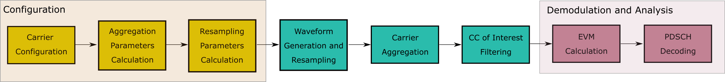
This example shows how to generate, aggregate, and demodulate multiple downlink carriers using 5G Toolbox™ features.
Introduction
This example generates an NR waveform with carrier aggregation (CA). To perform carrier aggregation, the example calculates the frequency offsets for the intraband contiguous CA case, as described in TS 38.104 Section 5.3A. The example also supports customized intraband noncontiguous and interband CA scenarios.
To generate an aggregated downlink waveform, the example configures a standard-compliant downlink fixed reference channel (FRC) for each component carrier. TS 38.101-1 Annex A.3 defines the physical downlink shared channel (PDSCH) FRCs for FR1 and TS 38.101-2 Annex A.3 defines the PDSCH FRCs for FR2. For the FRC waveform generation, you can specify the channel bandwidth, the subcarrier spacing, the modulation, the duplexing mode, and the cell ID. For more information on how to generate DL FRCs, see 5G NR-TM and FRC Waveform Generation.
After generating the component carriers (CCs), the example resamples the waveforms to a common sample rate and combines the CCs to generate the aggregated waveform.
Finally, the example filters and downsamples a selected CC to perform EVM measurements and PDSCH decoding.
Selection of Component Carrier Parameters
The vector ChannelBandwidths specifies the bandwidth for each CC. The length of this vector corresponds to the number of CCs. The elements of ChannelBandwidths must be in the set {5, 10, 15, 20, 25, 30, 40, 50, 60, 70, 80, 90 100} MHz for FR1 and in the set {50, 100, 200, 400} MHz for FR2. TS 38.101-1 Section 5.5A.1 Table 5.5A.1-1 and TS 38.101-2 Section 5.5A.1 Table 5.5A.1-1 list the valid combinations of bandwidths for FR1 and FR2 carrier aggregation, respectively.
If the ccSpacings vector is empty, the example calculates the spacings between consecutive carriers, ccSpacings, as described in TS 38.104. To select the spacings of your choice, add the spacings to the ccSpacings vector.
% Configure three carriers for the aggregation. You can select a different
% number of carriers by modifying the number of elements in the
% |channelBandwidths|, |SCSs|, |modulations|, and |nCellIDs| vectors.
frequencyRange = 'FR1'; % (FR1 or FR2)
channelRaster = 100; % Channel raster in kHz (15, 60 or 100)
channelBandwidths = [60 40 40]; % Channel bandwidths in MHz
                                % (5, 10, 15, 20, 25, 30, 40, 50, 60, 70, 80,
                                % 90 or 100 for FR1)
                                % (50, 100, 200 or 400 for FR2)
SCSs = [30 30 30]; % Subcarrier spacings in kHz
                   % (15, 30 or 60 for FR1)
                   % (60 or 120 for FR2)
modulations = {'QPSK' '64QAM' '256QAM'}; % ('QPSK', '64QAM' or '256QAM' for FR1)
                                         % ('QPSK', '16QAM' or '64QAM' for FR2)
nCellIDs = [1 2 3]; % Cell IDs
duplexMode = 'TDD'; % Duplex mode ('TDD' or 'FDD')
numSubframes = 10; % Number of subframes to generate per carrier

% Choose the spacings between consecutive carriers, |ccSpacings|, or leave
% the vector empty for calculating the spacings, as described in TS 38.104
% Section 5.3A
ccSpacings = []; % MHz

% Select the CC to demodulate
CCofInterest = 2;

% Verify the number of CCs, channel bandwidths, subcarrier spacings,
% modulations, and spacings. Additionally, check that the spacings are
% greater than 0.
hNRVerifyCarrierParameters(length(channelBandwidths),length(SCSs),...
    length(modulations),length(nCellIDs),ccSpacings);
Component Carrier Configuration
Generate a configuration structure for each CC using hNRReferenceWaveformGenerator. Store the configuration structures for all CCs in a cell array.
% Establish the number of component carriers
numCC = length(channelBandwidths);

% CC configuration
referenceChannel = cell(1,numCC);
wavegen = cell(1,numCC);
for i = 1:numCC
    % Select a reference channel, FRC, based on the chosen modulation and
    % frequency range
    referenceChannel{i} = strcat('DL-FRC-',frequencyRange,'-',modulations{i});

    % Create a generator object for the above PDSCH FRC reference channel
    wavegen{i} = hNRReferenceWaveformGenerator(referenceChannel{i},...
        channelBandwidths(i),SCSs(i),duplexMode,nCellIDs(i));
end
Carrier Aggregation Parameters Calculation
To perform the carrier aggregation, you must calculate the frequency parameters described in TS 38.104, Sections 5.3 and 5.4.
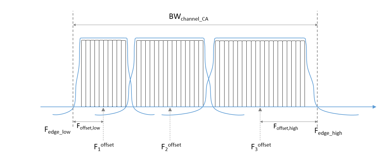
Fc_offsetis a vector containing the center frequency of each CC at basebandF_offset_lowis the frequency offset from the lowerFc_offsetto the lower aggregated bandwidth edgeF_offset_highis the frequency offset from the upperFc_offsetto the upper aggregated channel bandwidth edgeF_edge_lowis the lower edge of the aggregated channel bandwidthF_edge_highis the upper edge of the aggregated channel bandwidthBW_channel_CAis the aggregated channel bandwidth of all CCs
Center the lower carrier component at baseband (Fc_offset(1) = 0 Hz) and compute the center frequency for the rest of the CCs. To determine the center frequencies by following the method described in TS 38.104 Section 5.3A, you must calculate the minimum guardbands and the minimum CC spacings. Alternatively, to select your own center frequencies, choose a nonempty ccSpacings vector.
% Get the largest SCS configuration, |SCSConfig|, among the SCS
% configurations supported for each two consecutive channel bandwidths to
% obtain the minimum guardband, as described in TS 38.104 Section 5.4.1.2.
table = hGetGBTable(frequencyRange); % Minimum guardband table
if isequal(frequencyRange,'FR1')
    if any(channelBandwidths(:) == 5)
        SCSConfig = 1;
    else
        SCSConfig = 2;
    end
else
    SCSConfig = 3;
end

% Calculate the minimum guardband, as described in TS 38.104 Section 5.3.3
% Table 5.3.3-1 for FR1 and Table 5.3.3-1 for FR2, to obtain the minimum CC
% spacings.
minimumGuardBand = zeros(1,numCC);
NDLRB = zeros(1,numCC);
scs = strcat(num2str(2^SCSConfig*15),'kHz'); % Common SCS in kHz to extract
                                             % minimum guardband
for i = 1:numCC
    NDLRB(i) = wavegen{i}.Config.SCSCarriers{1}.NSizeGrid;
    minimumGuardBand(i) = table{{scs},{strcat(num2str(channelBandwidths(i)),...
        'MHz');}}; % kHz
    minimumGuardBand(i) = minimumGuardBand(i)*1e-3; % MHz
end

% Compute the minimum CC spacings, as defined in TS 38.104 Section
% 5.4.1.2. Use these spacings to calculate the center frequencies and for
% filtering each CC.
minCCSpacings = zeros(1,numCC-1); % Minimum CC spacing
for k = 2:numCC
    minCCSpacings(k-1) = hNRCarrierAggregationChannelSpacing( ...
        channelBandwidths(k-1), channelBandwidths(k), minimumGuardBand(k-1), ...
        minimumGuardBand(k),channelRaster,SCSConfig); % MHz
end

% Determine the center frequency for each CC with respect to 0 Hz.
% Initially, the lower carrier frequency is at baseband (Fc_offset(1) = 0 Hz).
Fc_offset = zeros(1,numCC);
if isempty(ccSpacings)
    ccSpacings = minCCSpacings;
end
for k = 2:numCC
    Fc_offset(k) = Fc_offset(k-1) + ccSpacings(k-1); % MHz
end
Calculate the frequency offsets from the lower and upper center frequencies to the lower and upper aggregated bandwidth edges, respectively, as described in TS 38.104 Section 5.3A.
F_offset_low = (NDLRB(1)*12+1)*(SCSs(1)*1e-3)/2 + minimumGuardBand(1); % MHz
F_offset_high = (NDLRB(end)*12-1)*(SCSs(end)*1e-3)/2 + minimumGuardBand(end); %MHz
Compute the lower and upper edges of the aggregated channel bandwidth, TS 38.104 Section 5.3A.
F_edge_low = Fc_offset(1) - F_offset_low; % MHz
F_edge_high = Fc_offset(end) + F_offset_high; % MHz
Calculate the aggregated channel bandwidth, TS 38.104 Section 5.3A
BW_channel_CA = F_edge_high - F_edge_low; % MHz
fprintf('BW_channel_CA: %0.4f MHz\n',BW_channel_CA);
BW_channel_CA: 141.0800 MHz
Determine the frequency shift to center the aggregated channel bandwidth at baseband (0 Hz).
shiftToCenter = -1*(BW_channel_CA/2 + F_edge_low);

% Center aggregated bandwidth at baseband
Fc_offset = Fc_offset + shiftToCenter;
F_edge_low = Fc_offset(1) - F_offset_low;
F_edge_high = Fc_offset(end) + F_offset_high;

% Display frequency band edges
fprintf('F_edge_low:  %0.4f MHz\n',F_edge_low);
F_edge_low: -70.5400 MHz
fprintf('F_edge_high: %0.4f MHz\n',F_edge_high);F_edge_high: 70.5400 MHz
fprintf('F_offset_low: %0.4f MHz\n',F_offset_low);F_offset_low: 30.7050 MHz
fprintf('F_offset_high: %0.4f MHz\n',F_offset_high);F_offset_high: 20.6750 MHz
% Display carrier frequencies
fprintf('\n');
for i = 1:numCC
    fprintf('Component Carrier %d:\n',i);
    fprintf('   Fc: %0.4f MHz\n', Fc_offset(i));
end
Component Carrier 1:
Fc: -39.8350 MHz
Component Carrier 2:
Fc: 9.9650 MHz
Component Carrier 3:
Fc: 49.8650 MHz
Oversampling Rate Calculation
Calculate the required oversampling factors for each component carrier, OSRs, to use a common sampling rate for the aggregated waveform.
% Obtain sample rates of the component carriers
CCSR = zeros(1,numCC);
carriers = cell(1,numCC);
for i = 1:numCC
    carriers{i} = nrCarrierConfig;
    carriers{i}.NCellID = nCellIDs(i);
    carriers{i}.NSizeGrid = NDLRB(i);
    carriers{i}.SubcarrierSpacing = SCSs(i);
    carriers{i}.CyclicPrefix = wavegen{i}.Config.BandwidthParts{1}.CyclicPrefix;
    info = nrOFDMInfo(carriers{i});
    CCSR(i) = info.SampleRate; % Hz
end

% Calculate the oversampling ratio for the largest BW CC to ensure the
% waveform occupies a maximum of 85% of the total bandwidth, |bwfraction|
bwfraction = 0.85; % Bandwidth utilization of 85%
OSR = (BW_channel_CA/bwfraction)/(max(CCSR)/1e6);

% To simplify the resampling operation, choose an oversampling ratio which
% is a power of 2: calculate the next power of two above OSR
OSR = 2^ceil(log2(OSR));

% Calculate the overall sample rate for the aggregated waveform
SR = OSR*max(CCSR); % Hz
fprintf('\nOutput sample rate: %0.4f Ms/s\n\n',SR/1e6);
Output sample rate: 245.7600 Ms/s
% Calculate the individual oversampling factors for the component carriers
OSRs = SR./CCSR;
Waveform Generation and Carrier Aggregation
Call the generateWaveform function from the hNRReferenceWaveformGenerator helper file to generate the waveform for each CC. Resample each carrier to a common sample rate. Finally, use comm.MultibandCombiner to frequency modulate the carriers to the appropriate center frequency, and aggregate the CCs to form the combined waveform.
% Generate and aggregate the component carriers
tmwaveinfo = cell(1,numCC);
waveInfo = cell(1,numCC);
resourcesInfo = cell(1,numCC);
clear waveform
for i = numCC:-1:1
    % Generate each CC
    [wf,waveInfo{i},resourcesInfo{i}] = generateWaveform(wavegen{i},...
        numSubframes);

    % Resample the CCs so that they have the same sample rate
    waveform(:,i) = resample(wf,OSRs(i),1)/OSRs(i);
end

% Aggregate all CC. comm.MultibandCombiner applies the frequency offsets
% and combines the resulting signals together.
carrierAggregator = comm.MultibandCombiner(InputSampleRate = SR,...
    FrequencyOffsets = Fc_offset*1e6,...
    OutputSampleRateSource = 'Property',...
    OutputSampleRate = SR);

waveform = carrierAggregator(waveform);
Plot Carrier Aggregated Spectrum
Display the spectrum of the carrier aggregated signal. This example does not upconvert the waveform to radio frequency (RF), the center of the aggregated bandwidth is at baseband (0 Hz).
% Create spectrum analyzer object
specPlot = spectrumAnalyzer("SampleRate",SR,...
                            "AveragingMethod","exponential",...
                            "ForgettingFactor",1, ...
                            "ChannelNames","Carrier aggregated signal",...
                            "ShowLegend",true,...
                            "Title","Power spectrum" );
% Plot spectrum
specPlot(waveform);

CC Demodulation and Filtering
Choose a CC, then demodulate, filter and downsample the CC of your choice, following these steps.
Bring the CC to baseband (0 Hz)
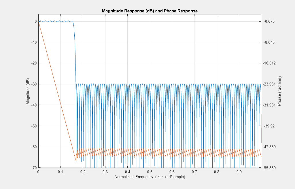
Calculate the passband and stopband frequencies of the filter
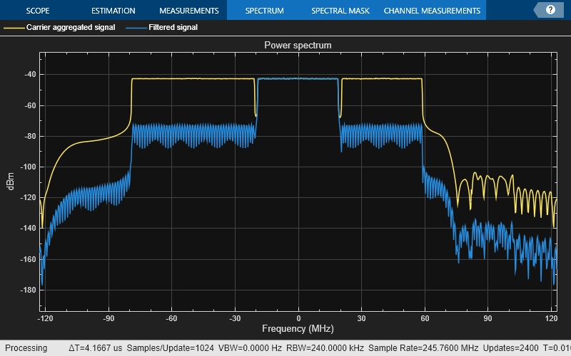
Filter out the neighboring CCs by using the designed filter and downsample the CC.
% Verify carrier of interest ID
if CCofInterest > numCC || CCofInterest <= 0 || mod(CCofInterest,1) ~= 0
    error('nr5g:NRDownlinkCarrierAggregationExample:CCOutOfRange',...
        'Cannot demodulate CC number %d, choose an integer number that falls between 1 and %d\n',...
        CCofInterest, numCC) ;
end
fprintf(1,'Extracting CC number %d: \n', CCofInterest);
Extracting CC number 2:
% Define downsampling filter order
filterOrder = 201;

% Precalculate the filter passband and stopband values for all CC
firPassbandVec = (NDLRB*12-1).*(SCSs*1e-3)/2 / (SR/1e6/2);
firStopbandVec = hNRCarrierAggregationStopband(minCCSpacings,NDLRB,SR,SCSs);

% Choose the passband and stopband values for the carrier of interest
firPassband = firPassbandVec(CCofInterest);
firStopband = firStopbandVec(CCofInterest);

% Pad signal with zeros to consider filter transient response length
waveform = [waveform; zeros(filterOrder*2,size(waveform,2))];

% Center the carrier of interest at 0 Hz
frequencyShifter = comm.PhaseFrequencyOffset(SampleRate = SR,...
    FrequencyOffset = -Fc_offset(CCofInterest)*1e6);
demodulatedCC = frequencyShifter(waveform);

% To ease the filter design requirements, apply the downsampling in two
% stages if necessary. Use a downsampling factor of 4 in the initial stage.
% If the quality of the resulting signal is not as required, consider a
% different filter design in this initial stage.
if (firStopband < 0.1)
    % Downsample by 4 in the initial stage
    SRC = 4;
    demodulatedCC = resample(demodulatedCC,1,SRC);
    % Update passband and stopband values
    firPassband = firPassband * SRC;
    firStopband = firStopband * SRC;
else
    % Do not apply an extra downsampling
    SRC = 1;
end

% Design the lowpass filter to filter out the CC of your choice
frEdges = [0 firPassband firStopband 1];
firFilter = dsp.FIRFilter;
firFilter.Numerator = firpm(filterOrder,frEdges,[1 1 0 0]);

% Display the response of the designed filter
freqz(firFilter);
% Filter the signal to extract the component of interest
rxWaveform  = firFilter(demodulatedCC);

filteredSpecPlot = spectrumAnalyzer("SampleRate",SR,...
                                    "AveragingMethod","exponential",...
                                    "ForgettingFactor",1,...
                                    "ChannelNames",{"Carrier aggregated signal", "Filtered signal"},...
                                    "ShowLegend",true,...
                                    "Title","Power spectrum");
filteredSpecPlot([demodulatedCC, rxWaveform]);
% Downsample the filtered carrier to its baseband rate
rxWaveform = downsample(rxWaveform,OSRs(CCofInterest)/SRC);
EVM Measurements
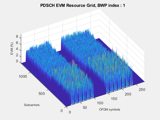
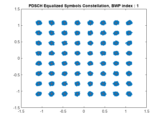
The hNRDownlinkEVM helper function returns the PDSCH EVM by performing synchronization, OFDM demodulation, channel estimation, and equalization. The function displays the EVM for each slot and frame and the overall EVM averaged over the entire input waveform. The function also plots these graphs: EVM per OFDM symbol, slot, subcarrier, and overall EVM.
% Parameterize the channel estimator configuration using the structure |cfg|
cfg = struct();
cfg.Evm3GPP = true; % To measure EVM as defined in TS 38.104, Annex B(FR1)
                    % / Annex C(FR2) set |Evm3GPP| to |true|.
cfg.TargetRNTIs = [];
cfg.PlotEVM = true;
cfg.DisplayEVM = true;
cfg.Label = wavegen{CCofInterest}.ConfiguredModel{1};

% Perform EVM measurements and plot results
[evmInfo,eqSym,refSym] = hNRDownlinkEVM(wavegen{CCofInterest}.Config,...
    rxWaveform,cfg);
EVM stats for BWP idx : 1
Low edge PDSCH RMS EVM, Peak EVM, slot 1: 2.797 7.912%
Low edge DM-RS RMS EVM, Peak EVM, slot 1: 2.748 6.320%
High edge PDSCH RMS EVM, Peak EVM, slot 1: 2.797 7.912%
High edge DM-RS RMS EVM, Peak EVM, slot 1: 2.748 6.320%
Low edge PDSCH RMS EVM, Peak EVM, slot 2: 2.797 7.472%
Low edge DM-RS RMS EVM, Peak EVM, slot 2: 2.787 6.044%
High edge PDSCH RMS EVM, Peak EVM, slot 2: 2.797 7.472%
High edge DM-RS RMS EVM, Peak EVM, slot 2: 2.787 6.044%
Low edge PDSCH RMS EVM, Peak EVM, slot 3: 2.820 7.541%
Low edge DM-RS RMS EVM, Peak EVM, slot 3: 2.758 6.577%
High edge PDSCH RMS EVM, Peak EVM, slot 3: 2.820 7.541%
High edge DM-RS RMS EVM, Peak EVM, slot 3: 2.758 6.577%
Low edge PDSCH RMS EVM, Peak EVM, slot 4: 2.802 7.551%
Low edge DM-RS RMS EVM, Peak EVM, slot 4: 2.744 5.920%
High edge PDSCH RMS EVM, Peak EVM, slot 4: 2.802 7.551%
High edge DM-RS RMS EVM, Peak EVM, slot 4: 2.744 5.920%
Low edge PDSCH RMS EVM, Peak EVM, slot 5: 2.800 7.593%
Low edge DM-RS RMS EVM, Peak EVM, slot 5: 2.766 6.222%
High edge PDSCH RMS EVM, Peak EVM, slot 5: 2.800 7.593%
High edge DM-RS RMS EVM, Peak EVM, slot 5: 2.766 6.222%
Low edge PDSCH RMS EVM, Peak EVM, slot 6: 2.817 7.948%
Low edge DM-RS RMS EVM, Peak EVM, slot 6: 2.731 6.452%
High edge PDSCH RMS EVM, Peak EVM, slot 6: 2.817 7.948%
High edge DM-RS RMS EVM, Peak EVM, slot 6: 2.731 6.452%
Low edge PDSCH RMS EVM, Peak EVM, slot 10: 2.790 8.589%
Low edge DM-RS RMS EVM, Peak EVM, slot 10: 2.747 6.573%
High edge PDSCH RMS EVM, Peak EVM, slot 10: 2.790 8.589%
High edge DM-RS RMS EVM, Peak EVM, slot 10: 2.747 6.573%
Low edge PDSCH RMS EVM, Peak EVM, slot 11: 2.788 7.994%
Low edge DM-RS RMS EVM, Peak EVM, slot 11: 2.750 6.581%
High edge PDSCH RMS EVM, Peak EVM, slot 11: 2.788 7.994%
High edge DM-RS RMS EVM, Peak EVM, slot 11: 2.750 6.581%
Low edge PDSCH RMS EVM, Peak EVM, slot 12: 2.806 8.468%
Low edge DM-RS RMS EVM, Peak EVM, slot 12: 2.780 6.476%
High edge PDSCH RMS EVM, Peak EVM, slot 12: 2.806 8.468%
High edge DM-RS RMS EVM, Peak EVM, slot 12: 2.780 6.476%
Low edge PDSCH RMS EVM, Peak EVM, slot 13: 2.819 7.483%
Low edge DM-RS RMS EVM, Peak EVM, slot 13: 2.731 6.164%
High edge PDSCH RMS EVM, Peak EVM, slot 13: 2.819 7.483%
High edge DM-RS RMS EVM, Peak EVM, slot 13: 2.731 6.164%
Low edge PDSCH RMS EVM, Peak EVM, slot 14: 2.810 7.989%
Low edge DM-RS RMS EVM, Peak EVM, slot 14: 2.757 6.405%
High edge PDSCH RMS EVM, Peak EVM, slot 14: 2.810 7.989%
High edge DM-RS RMS EVM, Peak EVM, slot 14: 2.757 6.405%
Low edge PDSCH RMS EVM, Peak EVM, slot 15: 2.797 8.219%
Low edge DM-RS RMS EVM, Peak EVM, slot 15: 2.796 6.437%
High edge PDSCH RMS EVM, Peak EVM, slot 15: 2.797 8.219%
High edge DM-RS RMS EVM, Peak EVM, slot 15: 2.796 6.437%
Low edge PDSCH RMS EVM, Peak EVM, slot 16: 2.803 7.699%
Low edge DM-RS RMS EVM, Peak EVM, slot 16: 2.740 6.302%
High edge PDSCH RMS EVM, Peak EVM, slot 16: 2.803 7.699%
High edge DM-RS RMS EVM, Peak EVM, slot 16: 2.740 6.302%
Averaged low edge RMS EVM, frame 0: 2.804%
Averaged high edge RMS EVM, frame 0: 2.804%
Averaged RMS EVM frame 0: 2.804%
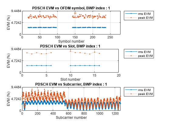
Averaged overall PDSCH RMS EVM: 2.804%
Overall PDSCH Peak EVM = 8.5895%
PDSCH Decoding
Decode the PDSCH of the recovered signal and check the resulting CRC for errors.
% Perform time synchronization on the input waveform
offset = nrTimingEstimate(carriers{CCofInterest},rxWaveform,...
    waveInfo{CCofInterest}.ResourceGridBWP);
rxWaveform = rxWaveform(1+offset:end,:);

% Perform OFDM demodulation
rxGrid = nrOFDMDemodulate(carriers{CCofInterest},rxWaveform);

% Get the allocated slots and OFDM symbols per slot
allocatedSlots = zeros(1,size(resourcesInfo{CCofInterest}.WaveformResources.PDSCH.Resources,2));
for i=1:length(allocatedSlots)
    allocatedSlots(i) = resourcesInfo{CCofInterest}.WaveformResources.PDSCH.Resources(i).NSlot;
end
L = carriers{CCofInterest}.SymbolsPerSlot; % OFDM symbols per slot

% Create a DLSCH decoder System object
decodeDLSCH = nrDLSCHDecoder;
decodeDLSCH.MultipleHARQProcesses = false;
decodeDLSCH.TargetCodeRate = wavegen{CCofInterest}.Config.PDSCH{1}.TargetCodeRate;
decodeDLSCH.LDPCDecodingAlgorithm = 'Normalized min-sum';
decodeDLSCH.MaximumLDPCIterationCount = 6;

for NSlot=1:length(allocatedSlots)
    % Extract slot
    SlotID = allocatedSlots(NSlot);
    rxSlot = rxGrid(:,(1:L)+(SlotID*L),:);
    refSlot = waveInfo{CCofInterest}.ResourceGridBWP(:,(1:L)+(SlotID*L),:);

    % Perform channel estimation
    [estChannelGrid,noiseEst] = nrChannelEstimate(carriers{CCofInterest},...
        rxSlot,refSlot);

    % Get PDSCH resource elements from the received grid and channel estimate
    pdschIndices = resourcesInfo{CCofInterest}.WaveformResources.PDSCH.Resources(NSlot).ChannelIndices;
    [pdschRx,pdschHest] = nrExtractResources(pdschIndices,rxSlot,estChannelGrid);

    % Perform equalization
    [pdschEq,csi] = nrEqualizeMMSE(pdschRx,pdschHest,noiseEst);

    % Perform layer demapping, symbol demodulation, and descrambling
    modulation = wavegen{CCofInterest}.Config.PDSCH{1}.Modulation;
    RNTI = wavegen{CCofInterest}.Config.PDSCH{1}.RNTI;
    [dlschLLRs,rxSymbols] = nrPDSCHDecode(pdschEq,modulation,...
        carriers{CCofInterest}.NCellID,RNTI,noiseEst);

    % Scale LLRs by CSI
    csi = nrLayerDemap(csi); % CSI layer demapping
    NumCW = size(resourcesInfo{CCofInterest}.WaveformResources.PDSCH.Resources(NSlot).Codeword,2);
    for cwIdx = 1:NumCW
        Qm = length(dlschLLRs{cwIdx})/length(rxSymbols{cwIdx}); % Bits per symbol
        csi{cwIdx} = repmat(csi{cwIdx}.',Qm,1);   % Expand by each bit per symbol
        dlschLLRs{cwIdx} = dlschLLRs{cwIdx} .* csi{cwIdx}(:);   % Scaled symbols
    end

    % Calculate the transport block sizes for the codewords in the slot
    trBlkSize = resourcesInfo{CCofInterest}.WaveformResources.PDSCH.Resources(NSlot).TransportBlockSize;

    % Decode the DL-SCH transport channel
    decodeDLSCH.TransportBlockLength = trBlkSize;
    NLayers = wavegen{CCofInterest}.Config.PDSCH{1}.NumLayers;
    RVSequence = wavegen{CCofInterest}.Config.PDSCH{1}.RVSequence;
    [decbits,crc] = decodeDLSCH(dlschLLRs,modulation,NLayers,RVSequence);

    % Display the CRC status
    if crc
        disp(['Slot ' num2str(SlotID) ': CRC failed']);
    else
        disp(['Slot ' num2str(SlotID) ': CRC passed']);
    end
end
Slot 1: CRC passed
Slot 2: CRC passed
Slot 3: CRC passed
Slot 4: CRC passed
Slot 5: CRC passed
Slot 6: CRC passed
Slot 10: CRC passed
Slot 11: CRC passed
Slot 12: CRC passed
Slot 13: CRC passed
Slot 14: CRC passed
Slot 15: CRC passed
Slot 16: CRC passed
Bibliography
3GPP TS 38.104 "NR; Base Station (BS) radio transmission and reception" 3rd Generation Partnership Project; Technical Specification Group Radio Access Network.
3GPP TS 38.101-1 "NR; User Equipment (UE) radio transmission and reception; Part 1: Range 1 Standalone." 3rd Generation Partnership Project; Technical Specification Group Radio Access Network.
3GPP TS 38.101-2 "NR; User Equipment (UE) radio transmission and reception: Part 2: Range 2 Standalone." 3rd Generation Partnership Project; Technical Specification Group Radio Access Network.
Local Functions
function table = hGetGBTable(frequencyRange)
%hGetGBTable Minimum guardband table
%   GB = hGetGBTable(FREQUENCYRANGE) extracts the minimum guardband, GB, in
%   kHz for the frequency range, FREQUENCYRANGE. For FR1, the table is
%   described in TS 38.104 Table 5.3.3-1 and for FR2, the table is
%   described in TS 38.104 Table 5.3.3-2.

    if isequal(frequencyRange,'FR1')
        % GB MHz    5       10     15     20     25     30     35     40     45     50    60    70    80    90    100
        gbTable = [242.5   312.5  382.5	 452.5  522.5  592.5  572.5  552.5  712.5  692.5  NaN   NaN   NaN   NaN   NaN;     % 15 kHz
                   505	   665	  645	 805	785    945    925    905    1065   1045   825   965   925   885   845;     % 30 kHz
                   NaN     1010	  990	 1330	1310   1290   1630   1610   1590   1570   1530  1490  1450  1410  1370];   % 60 kHz

         % Package GB array into a table
         table = array2table(gbTable,"RowNames",["15kHz","30kHz","60kHz"],"VariableNames",["5MHz", "10MHz", "15MHz", "20MHz", "25MHz", "30MHz", "35MHz", "40MHz", "45MHz", "50MHz", "60MHz", "70MHz", "80MHz", "90MHz", "100MHz"]);
         table.Properties.Description = 'TS 38.104 Table 5.3.3-1: Minimum guardband (kHz) FR1';
    else
         % GB MHz   50    100    200    400
        gbTable = [1210	  2450	 4930	NaN;      % 60 kHz
                   1900	  2420	 4900	9860];    % 120 kHz

         % Package GB array into a table
         table = array2table(gbTable,"RowNames",["60kHz","120kHz"],"VariableNames",["50MHz", "100MHz", "200MHz", "400MHz"]);
         table.Properties.Description = 'TS 38.104 Table 5.3.3-2: Minimum guardband (kHz) FR2';
    end
end

function spacing = hNRCarrierAggregationChannelSpacing(BW1,BW2,GB1,GB2,channelRaster,mu)
%hNRCarrierAggregationChannelSpacing NR nominal channel spacing
%   SPACING = hNRCarrierAggregationChannelSpacing(BW1,BW2,GB1,GB2,CHANNELRASTER,MU)
%   is the NR nominal channel spacing in MHz between two adjacent carriers
%   with bandwidths BW1 and BW2, also expressed in MHz. GB1 and GB2 are the
%   minimum guardbands for bandwidth BW1 and bandwidth BW2, respectively.
%   The NR nominal channel calculation depends on the channel raster,
%   CHANNELRASTER, and the subcarrier spacing (SCS) configuration, MU,
%   which is the largest SCS value among the SCS configurations supported
%   for both of the channel bandwidths.

    switch channelRaster
        case 15
            % Nominal channel spacing (MHz) as defined in TS 38.104 5.4.1.2
            % for NR operating bands with a 15 kHz channel raster
            n = mu;
            spacing = floor((BW1+BW2-2*abs(GB1-GB2))/(0.015*2^(n+1)))*(0.015*2^(n));
        case 60
            % Nominal channel spacing (MHz) as defined in TS 38.104 5.4.1.2
            % for NR operating bands with a 60 kHz channel raster
            n = mu-2;
            spacing = floor((BW1+BW2-2*abs(GB1-GB2))/(0.06*2^(n+1)))*(0.06*2^(n));
        case 100
            % Nominal channel spacing (MHz) as defined in TS 38.104 5.4.1.2
            % for NR operating bands with a 100 kHz channel raster
            spacing = floor((BW1+BW2-2*abs(GB1-GB2))/0.6)*0.3;
        otherwise
            error('nr5g:hNRCarrierAggregationChannelSpacing:IncorrectRaster','The channel raster (%.2fkHz) must be 15, 60 or 100kHz.',channelRaster);
    end
end

function stopband = hNRCarrierAggregationStopband(ccSpacing,NDLRB,SR,SCS)
%hNRCarrierAggregationStopband Stopband values for NR carrier selection
%   STOPBAND = hNRCarrierAggregationStopband(CCSPACING,NDLRB,SR,SCS)
%   calculates the stopband values, STOPBAND, in a 5G carrier aggregation
%   scenario given the component carrier spacing vector CCSPACING, the
%   vector of bandwidths for each CC, NDLRB, the sampling rate of the
%   aggregated waveform, SR, and the subcarrier spacing of each component
%   carrier, SCS.

    numCC = length(NDLRB);
    stopband = zeros(numCC,1);

    for i = 1:numCC
        % Compute two possible stopbands based on spacing with component
        % carrier before and after
        if (i > 1)
            % There is a carrier component before the one being considered
            frStopband1 = ccSpacing(i-1)-(NDLRB(i-1)*12-2)*(SCS(i-1)*1e-3)/2;
        else
            frStopband1 = NaN;
        end
        if (i < numCC)
            % There is a carrier component after the one being considered
            frStopband2 = ccSpacing(i)-(NDLRB(i+1)*12-2)*(SCS(i+1)*1e-3)/2;
        else
            frStopband2 = NaN;
        end
        % Take the minimum value
        stopband(i) = min(frStopband1,frStopband2) / (SR/1e6/2);
    end
end

function hNRVerifyCarrierParameters(numberBWs,numberSCSs,numberModulations,numberCellIDs,spacings)
%hNRVerifyCarrierParameters Carrier aggregation parameters verification
%   hNRVerifyCarrierParameters(NUMBERBWS,NUMBERSCSS,NUMBERMODULATIONS,NUMBERCELLIDS,SPACINGS)
%   verifies if the number of channel bandwidths, NUMBERBWS, subcarrier
%   spacings, NUMBERSCSS, modulations, NUMBERMODULATIONS, and cell IDs,
%   NUMBERCELLIDS, are the same. This function also checks the spacing
%   between two consecutive carriers, SPACINGS.

    % Verify that there is a channel bandwidth, a subcarrier spacing and a
    % modulation per carrier
    if ~(numberBWs == numberSCSs && numberSCSs == numberModulations && numberModulations == numberCellIDs)
        error('nr5g:hNRVerifyCarrierParameters:NumberCCConfigParams','Please specify the same number of channel bandwidths (%d), SCSs (%d), modulations (%d) and cell IDs (%d).',numberBWs,numberSCSs,numberModulations,numberCellIDs);
    end

    % Check if there are at least two component carriers
    numCC = numberBWs;
    if numCC<2
        error('nr5g:hNRVerifyCarrierParameters:OneCarrier','Please specify more than one channel bandwidth value.');
    end

    % Check the number of spacings and their values
    if ~isempty(spacings)
        if length(spacings) ~= numCC-1
            error('nr5g:hNRVerifyCarrierParameters:NumberSpacings','The number of CC spacings (%d) is not compatible with the number of carriers (%d). Please specify one CC spacing per two consecutive carriers.',length(spacings),numCC);
        end
        if any(spacings<=0)
            error('nr5g:hNRVerifyCarrierParameters:SpacingsLowerEqualZero','The CC spacings should be greater than 0.');
        end
    end
end