5G NR Downlink Vector Waveform Generation
This example shows how to configure and generate a 5G NR downlink vector waveform for a baseband component carrier by using the nrWaveformGenerator function.
Introduction
This example shows how to parameterize and generate a 5G new radio (NR) downlink waveform by using the nrWaveformGenerator function. The generated waveform contains these channels and signals.
PDSCH and its associated DM-RS and PT-RS
PDCCH and its associated DM-RS
PBCH and its associated DM-RS
PSS and SSS
CSI-RS
This example demonstrates how to parameterize and generate a baseband component carrier waveform characterized by multiple subcarrier spacing (SCS) carriers and bandwidth parts (BWP). You can generate multiple instances of the physical downlink shared channel (PDSCH), the physical downlink control channel (PDCCH), and the channel state information reference signal (CSI-RS) over the different BWPs. You can configure sets of control resource sets (CORESETs) and search space monitoring opportunities for mapping the PDCCHs. This example does not apply precoding to the physical channels and signals.
Waveform and Carrier Configuration
Use the nrDLCarrierConfig object to parameterize the baseband waveform generation. This object contains a set of additional objects associated with the waveform channels and signals and enables you to set these downlink carrier configuration parameters.
Label for this DL carrier configuration
SCS carrier bandwidth in resource blocks
Carrier cell ID
Length of the generated waveform in subframes
Windowing
Sample rate of the OFDM-modulated waveform
Carrier frequency for symbol phase compensation
You can control SCS carrier bandwidths and guardbands using the NStartGrid and NSizeGrid properties of the nrSCSCarrierConfig object.
waveconfig = nrDLCarrierConfig;    % Create a downlink carrier configuration object
waveconfig.Label = 'DL carrier 1'; % Label for this downlink waveform configuration
waveconfig.NCellID = 0;            % Cell identity
waveconfig.ChannelBandwidth = 40;  % Channel bandwidth (MHz)
waveconfig.FrequencyRange = 'FR1'; % 'FR1' or 'FR2'
waveconfig.NumSubframes = 10;      % Number of 1 ms subframes in generated waveform (1, 2, 4, 8 slots per 1 ms subframe, depending on SCS)
waveconfig.WindowingPercent = 0;   % Percentage of windowing relative to FFT length
waveconfig.SampleRate = [];        % Sample rate of the OFDM modulated waveform
waveconfig.CarrierFrequency = 0;   % Carrier frequency in Hz. This property is used for symbol phase
                                   % compensation before OFDM modulation

% Define a set of SCS specific carriers, using the maximum sizes for a
% 40 MHz NR channel. See TS 38.101-1 for more information on defined
% bandwidths and guardband requirements
scscarriers = {nrSCSCarrierConfig,nrSCSCarrierConfig};
scscarriers{1}.SubcarrierSpacing = 15;
scscarriers{1}.NSizeGrid = 216;
scscarriers{1}.NStartGrid = 0;

scscarriers{2}.SubcarrierSpacing = 30;
scscarriers{2}.NSizeGrid = 106;
scscarriers{2}.NStartGrid = 1;
SS Burst
In this section you can set the parameters for the signal synchronization (SS) burst. The numerology of the SS burst can be different from other parts of the waveform. This is specified via the block pattern parameter, as specified in TS 38.213 Section 4.1. A bitmap specifies the blocks to transmit in a 5 ms half-frame burst. You can also set the periodicity in milliseconds and the power of the burst. For a full list of configurable SS burst properties, see nrWavegenSSBurstConfig.
% SS burst configuration
ssburst = nrWavegenSSBurstConfig;
ssburst.Enable = 1;                     % Enable SS Burst
ssburst.Power = 0;                      % Power scaling in dB
ssburst.BlockPattern = 'Case B';        % Case B (30kHz) subcarrier spacing
ssburst.TransmittedBlocks = [1 1 1 1];  % Bitmap indicating blocks transmitted in a 5ms half-frame burst
ssburst.Period = 20;                    % SS burst set periodicity in ms (5, 10, 20, 40, 80, 160)
ssburst.NCRBSSB = [];                   % Frequency offset of SS burst (CRB), use [] for the waveform center
BWPs
A BWP is formed by a set of contiguous resources sharing a numerology on a given SCS carrier. You can define multiple BWPs using a cell array. Each element in the cell array of nrWavegenBWPConfig objects defines a BWP. For each BWP, you can specify the SCS, the cyclic prefix (CP) length, and the bandwidth. The SubcarrierSpacing property links the BWP to one of the SCS specific carriers defined earlier. The NStartBWP property controls the location of the BWP in the carrier, relative to point A. NStartBWP is expressed in common resource blocks (CRB) in terms of the BWP numerology. Different BWPs can overlap with each other.
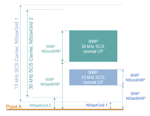
% BWP configurations
bwp = {nrWavegenBWPConfig,nrWavegenBWPConfig};
bwp{1}.BandwidthPartID = 1;        % BWP ID
bwp{1}.Label = 'BWP 1 @ 15 kHz';   % Label for this BWP
bwp{1}.SubcarrierSpacing = 15;     % BWP subcarrier spacing
bwp{1}.CyclicPrefix = 'Normal';    % BWP cyclic prefix for 15 kHz
bwp{1}.NSizeBWP = 25;              % Size of BWP in PRBs
bwp{1}.NStartBWP = 12;             % Position of BWP, relative to point A, in CRBs

bwp{2}.BandwidthPartID = 2;        % BWP ID
bwp{2}.Label = 'BWP 2 @ 30 kHz';   % Label for this BWP
bwp{2}.SubcarrierSpacing = 30;     % BWP subcarrier spacing
bwp{2}.CyclicPrefix = 'Normal';    % BWP cyclic prefix for 30 kHz
bwp{2}.NSizeBWP = 50;              % Size of BWP in PRBs
bwp{2}.NStartBWP = 51;             % Position of BWP, relative to point A, in CRBs
CORESET and Search Space Configuration
Specify the CORESET and the PDCCH search space configuration. The CORESET and search spaces specify the possible locations (in time and frequency) of the control channel transmissions for a given numerology. Each element in the cell array of nrCORESETConfig objects defines a CORESET and each element in the cell array of nrSearchSpaceConfig objects defines a search space.
Set these parameters for each CORESET and search space.
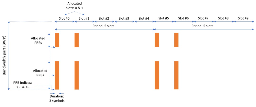
The OFDM symbols which specify the first symbol of each CORESET monitoring opportunity in a slot.
The duration of the block of allocated slots within a period.
Periodicity of the allocation pattern.
The CORESET duration in symbols, either 1, 2 or 3.
A bitmap defining the allocated physical resource blocks (PRB) of the CORESET. The CORESET frequency allocation is defined in blocks of 6 PRBs, aligned in CRB numbering, relative to point A. Each bit in the bitmap selects all 6 PRBs in the CRB aligned block that contains it.
CCE-to-REG mapping which can be 'interleaved' or 'noninterleaved'.
Resource element group (REG) bundle size (L), either (2,6) or (3,6), based on CORESET duration.
Interleaver size, either 2, 3, or 6.
Shift index, a scalar value in the range 0...274.
The figure below shows the meaning of some of the CORESET parameters.
% CORESET and search space configurations
coresets = {nrCORESETConfig};
coresets{1}.CORESETID = 1;                      % CORESET ID
coresets{1}.Duration = 3;                       % CORESET symbol duration (1,2,3)
coresets{1}.FrequencyResources = [1 1 0 1];     % Bitmap indicating blocks of 6 PRB for CORESET (RRC - frequencyDomainResources)
coresets{1}.CCEREGMapping = 'noninterleaved';   % Mapping: 'interleaved' or 'noninterleaved'
coresets{1}.REGBundleSize = 3;                  % L (2,6) or (3,6)
coresets{1}.InterleaverSize = 2;                % R (2,3,6)
coresets{1}.ShiftIndex = waveconfig.NCellID;    % Set to NCellID

searchspaces = {nrSearchSpaceConfig};
searchspaces{1}.SearchSpaceID = 1;              % Search space ID
searchspaces{1}.CORESETID = 1;                  % CORESET associated with this search space
searchspaces{1}.SearchSpaceType = 'ue';         % Search space type, 'ue' or 'common'
searchspaces{1}.SlotPeriodAndOffset = [5 0];    % Allocated slot period and slot offset of search space pattern
searchspaces{1}.Duration = 2;                   % Number of slots in the block of slots in pattern period
searchspaces{1}.StartSymbolWithinSlot = 0;      % First symbol of each CORESET monitoring opportunity in a slot
searchspaces{1}.NumCandidates = [8 8 4 2 0];    % Number of candidates at each AL (set to 0 if the AL doesn't fit in CORESET)
PDCCH Instances Configuration
Specify the set of PDCCH transmission instances in the waveform by using a cell array. Each element in the cell array of nrWavegenPDCCHConfig objects defines a sequence of PDCCH instances.
Set these parameters for each PDCCH sequence.
Enable or disable this PDCCH sequence.
Specify a label for this PDCCH sequence.
Specify the BWP carrying the PDCCH. The PDCCH uses the SCS specified for this BWP.
Power scaling in dB.
Enable or disable downlink control information (DCI) channel coding.
Allocated search spaces within the CORESET monitoring occasion sequence.
Search space (and CORESET) that carries the PDCCH instances.
Period of the allocation in slots. Empty period indicates no repetition of the slot pattern.
The aggregation level (AL) of the PDCCH (number of control channel elements (CCEs)).
The allocated candidate which specifies the CCE used for the transmission of the PDCCH.
RNTI.
Scrambling NID for this PDCCH and its associated DM-RS.
DM-RS power boosting in dB.
DCI message payload size.
DCI message data source. You can use an array of bits or one of these standard PN sequences:
'PN9-ITU','PN9','PN11','PN15','PN23'. You can specify the seed for the generator as a cell array in the form{'PN9', seed}. If you do not specify a seed, the generator is initialized with all ones.
pdcch = {nrWavegenPDCCHConfig};
pdcch{1}.Enable = 1 ;                     % Enable PDCCH sequence
pdcch{1}.Label = 'UE 1 - PDCCH @ 15 kHz'; % Label for this PDCCH sequence
pdcch{1}.BandwidthPartID = 1;             % Bandwidth part of PDCCH transmission
pdcch{1}.Power = 1.1;                     % Power scaling in dB
pdcch{1}.Coding = 1;                      % Enable DCI coding
pdcch{1}.SearchSpaceID = 1;               % Search space
pdcch{1}.SlotAllocation = 0;              % Allocated slots indices for PDCCH sequence
pdcch{1}.Period = 5;                      % Allocation period in slots
pdcch{1}.AggregationLevel = 8;            % Aggregation level (1,2,4,8,16 CCEs)
pdcch{1}.AllocatedCandidate = 1;          % PDCCH candidate in search space (1 based)
pdcch{1}.RNTI = 11;                       % RNTI
pdcch{1}.DMRSScramblingID = 1;            % PDCCH and DM-RS scrambling NID
pdcch{1}.DMRSPower = 0;                   % Additional DM-RS power boosting in dB
pdcch{1}.DataBlockSize = 20;              % DCI payload size
pdcch{1}.DataSource = 'PN9';              % DCI data source
PDSCH Instances Configuration
Specify the set of PDSCH transmission instances in the waveform by using a cell array. Each element in the cell array of nrWavegenPDSCHConfig objects defines a sequence of PDSCH instances. This example defines two PDSCH sequences that model two user equipment (UE) transmissions.
General Parameters
Set these parameters for each PDSCH sequence.
Enable or disable this PDSCH sequence.
Specify a label for this PDSCH sequence.
Specify the BWP carrying the PDSCH. The PDSCH uses the SCS specified for this BWP.
Power scaling in dB.
Enable or disable the DL-SCH transport channel coding.
Transport block data source. You can use an array of bits or one of these standard PN sequences:
'PN9-ITU','PN9','PN11','PN15','PN23'. You can specify the seed for the generator as a cell array in the form{'PN9', seed}. If you do not specify a seed, the generator is initialized with all ones.Target code rate used to calculate the transport block sizes.
Overhead parameter.
Symbol modulation.
Number of layers.
Redundancy version (RV) sequence.
Enable or disable the interleaving of the virtual to physical resource block mapping.
Bundle size for the interleaved map, specified by the higher layer parameter vrb-ToPRB-Interleaver.
pdsch = {nrWavegenPDSCHConfig};           % Create a PDSCH configuration object for the first UE
pdsch{1}.Enable = 1;                      % Enable PDSCH sequence
pdsch{1}.Label = 'UE 1 - PDSCH @ 15 kHz'; % Label for this PDSCH sequence
pdsch{1}.BandwidthPartID = 1;             % Bandwidth part of PDSCH transmission
pdsch{1}.Power  = 0;                      % Power scaling in dB
pdsch{1}.Coding = 1;                      % Enable the DL-SCH transport channel coding
pdsch{1}.DataSource = 'PN9';              % Channel data source
pdsch{1}.TargetCodeRate = 0.4785;         % Code rate used to calculate transport block sizes
pdsch{1}.XOverhead = 0;                   % Rate matching overhead
pdsch{1}.Modulation = 'QPSK';             % 'QPSK', '16QAM', '64QAM', '256QAM'
pdsch{1}.NumLayers = 2;                   % Number of PDSCH layers
pdsch{1}.RVSequence = [0 2 3 1];          % RV sequence to be applied cyclically across the PDSCH allocation sequence
pdsch{1}.VRBToPRBInterleaving = 0;        % Disable interleaved resource mapping
pdsch{1}.VRBBundleSize = 2;               % vrb-ToPRB-Interleaver parameter
Allocation
This figure shows the parameters of the PDSCH allocation.
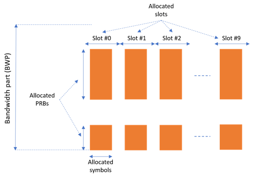
You can set these parameters to control the PDSCH allocation. These parameters are relative to the BWP. The specified PDSCH allocation will avoid the locations used for the SS burst.
Symbols in a slot allocated to each PDSCH instance.
Slots in a frame used for the sequence of PDSCH.
Period of the allocation in slots. Empty period indicates no repetition of the slot pattern.
The allocated PRBs relative to the BWP.
RNTI. This value is used to link the PDSCH to an instance of the PDCCH.
NID for scrambling the PDSCH bits.
pdsch{1}.SymbolAllocation = [2 9];    % First symbol and length
pdsch{1}.SlotAllocation = 0:9;        % Allocated slot indices for PDSCH sequence
pdsch{1}.Period = 15;                 % Allocation period in slots
pdsch{1}.PRBSet = [0:5, 10:20];       % PRB allocation
pdsch{1}.RNTI = 11;                   % RNTI for the first UE
pdsch{1}.NID = 1;                     % Scrambling for data part
CORESETs and sets of PRB can be specified for rate matching around, if required
The PDSCH can be rate matched around one or more CORESETs.
The PDSCH can be rate matched around other resource allocations.
pdsch{1}.ReservedCORESET = 1;           % Rate matching pattern, defined by CORESET IDs
pdsch{1}.ReservedPRB{1}.PRBSet = [];    % Rate matching pattern, defined by set of PRB (RRC 'bitmaps')
pdsch{1}.ReservedPRB{1}.SymbolSet = [];
pdsch{1}.ReservedPRB{1}.Period = [];
PDSCH DM-RS Configuration
Set the DM-RS parameters.
% Antenna port and DM-RS configuration (TS 38.211 section 7.4.1.1)
pdsch{1}.MappingType = 'A';                % PDSCH mapping type ('A'(slot-wise),'B'(non slot-wise))
pdsch{1}.DMRSPower = 0;                    % Additional power boosting in dB

pdsch{1}.DMRS.DMRSConfigurationType = 2;   % DM-RS configuration type (1,2)
pdsch{1}.DMRS.NumCDMGroupsWithoutData = 1; % Number of DM-RS CDM groups without data. The value can be one of the set {1,2,3}
pdsch{1}.DMRS.DMRSPortSet = [];            % DM-RS antenna ports used ([] gives port numbers 0:NumLayers-1)
pdsch{1}.DMRS.DMRSTypeAPosition = 2;       % Mapping type A only. First DM-RS symbol position (2,3)
pdsch{1}.DMRS.DMRSLength = 1;              % Number of front-loaded DM-RS symbols (1(single symbol),2(double symbol))
pdsch{1}.DMRS.DMRSAdditionalPosition = 0;  % Additional DM-RS symbol positions (max range 0...3)
pdsch{1}.DMRS.NIDNSCID = 1;                % Scrambling identity (0...65535)
pdsch{1}.DMRS.NSCID = 0;                   % Scrambling initialization (0,1)
PDSCH PT-RS Configuration
Set the PT-RS parameters.
% PT-RS configuration (TS 38.211 section 7.4.1.2)
pdsch{1}.EnablePTRS = 0;             % Enable or disable the PT-RS (1 or 0)
pdsch{1}.PTRSPower = 0;              % Additional PT-RS power boosting in dB

pdsch{1}.PTRS.TimeDensity = 1;       % Time density (L_PT-RS) of PT-RS (1,2,4)
pdsch{1}.PTRS.FrequencyDensity = 2;  % Frequency density (K_PT-RS) of PT-RS (2,4)
pdsch{1}.PTRS.REOffset = '00';       % PT-RS resource element offset ('00','01','10','11')
pdsch{1}.PTRS.PTRSPortSet = 0;       % PT-RS antenna ports must be a subset of DM-RS ports
When PT-RS is enabled, the DM-RS ports must be in the range from 0 to 3 for DM-RS configuration type 1, and in the range from 0 to 5 for DM-RS configuration type 2. Nominally, the antenna port of PT-RS is the lowest DM-RS port number.
Specifying Multiple PDSCH Instances
Specify the second PDSCH sequence for the second BWP.
pdsch{2} = pdsch{1};                   % Create a PDSCH configuration object for the second UE
pdsch{2}.Enable = 1;
pdsch{2}.Label = 'UE 2 - PDSCH @ 30 kHz';
pdsch{2}.BandwidthPartID = 2;          % PDSCH mapped to the second BWP
pdsch{2}.RNTI = 12;                    % RNTI for the second UE
pdsch{2}.SymbolAllocation = [0 12];
pdsch{2}.SlotAllocation = [2:4, 6:20];
pdsch{2}.PRBSet  = [25:30, 35:38];     % PRB allocation, relative to BWP
CSI-RS Instances Configuration
This section configures CSI-RS in the waveform. Each element in the cell array of nrWavegenCSIRSConfig objects defines a set of CSI-RS resources associated with a BWP. Define two disabled sets of CSI-RS resources.
General Parameters
Set these parameters for a set of CSI-RS resources.
Enable or disable this set of CSI-RS resources.
Specify a label for this set of CSI-RS resources.
Specify the BWP carrying this set of CSI-RS resources. The CSI-RS resource(s) configuration uses the SCS specified for this BWP.
Specify the power scaling in dB. Providing a scalar defines the power scaling for a single CSI-RS resource or all configured CSI-RS resources. Providing a vector defines a separate power level for each of the CSI-RS resources.
csirs = {nrWavegenCSIRSConfig};
csirs{1}.Enable = 0;
csirs{1}.Label = 'CSI-RS @ 15 kHz';
csirs{1}.BandwidthPartID = 1;
csirs{1}.Power = 3; % Power scaling in dB
CSI-RS Configuration
You can configure these parameters for one or more zero-power (ZP) or non-zero-power (NZP) CSI-RS resource configurations.
Type of CSI-RS resource(s) ('nzp','zp').
Row number corresponds to CSI-RS resource(s) as defined in TS 38.211 Table 7.4.1.5.3-1 (1...18).
Frequency density of CSI-RS resource(s). It can be
'one','three','dot5even', or'dot5odd'.Subcarrier locations of CSI-RS resource(s) within a resource block (RB)
Number of RBs allocated to CSI-RS resource(s) (1...275).
Starting RB index of CSI-RS resource(s) allocation relative to the carrier resource grid (0...274).
OFDM symbol locations of CSI-RS resource(s) within a slot.
The period and offset of slots (0-based) of CSI-RS resource(s). This parameter can be a vector or a cell array of vectors. In the latter case, each cell corresponds to an individual CSI-RS resource. In case of a vector, the same set of slots is used for all CSI-RS resources.
Scrambling identity corresponds to CSI-RS resource(s) for pseudo-random sequence generation (0...1023).
csirs{1}.CSIRSType = {'nzp','zp'};
csirs{1}.RowNumber = [3 5];
csirs{1}.Density = {'one','one'};
csirs{1}.SubcarrierLocations = {6 4};
csirs{1}.NumRB = 25;
csirs{1}.RBOffset = 12;
csirs{1}.SymbolLocations = {13 9};
csirs{1}.CSIRSPeriod = {[5 0], [5 0]};
csirs{1}.NID = 5;
Specifying Multiple CSI-RS Instances
Specify the second set of CSI-RS resources for the second BWP.
csirs{2} = nrWavegenCSIRSConfig;
csirs{2}.Enable = 0;
csirs{2}.Label = 'CSI-RS @ 30 kHz';
csirs{2}.BandwidthPartID = 2;
csirs{2}.Power = 3; % Power scaling in dB
csirs{2}.CSIRSType = {'nzp','nzp'};
csirs{2}.RowNumber = [1 1];
csirs{2}.Density = {'three','three'};
csirs{2}.SubcarrierLocations = {0 0};
csirs{2}.NumRB = 50;
csirs{2}.RBOffset = 50;
csirs{2}.SymbolLocations = {6 10};
csirs{2}.CSIRSPeriod = {[10 1], [10 1]};
csirs{2}.NID = 0;
Waveform Generation
Assign all the channel and signal parameters into the main carrier configuration object nrDLCarrierConfig, then generates and plot the waveform.
waveconfig.SSBurst = ssburst;
waveconfig.SCSCarriers = scscarriers;
waveconfig.BandwidthParts = bwp;
waveconfig.CORESET = coresets;
waveconfig.SearchSpaces = searchspaces;
waveconfig.PDCCH = pdcch;
waveconfig.PDSCH = pdsch;
waveconfig.CSIRS = csirs;

% Generate complex baseband waveform
[waveform,info] = nrWaveformGenerator(waveconfig);
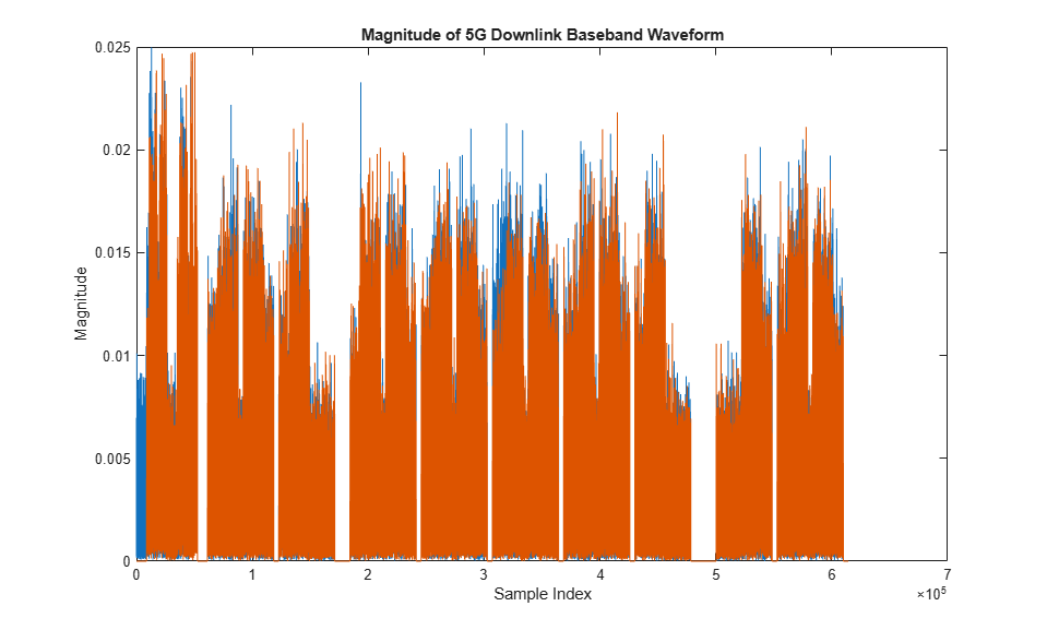
Plot the magnitude of the baseband waveform for the set of antenna ports defined.
figure;
plot(abs(waveform));
title('Magnitude of 5G Downlink Baseband Waveform');
xlabel('Sample Index');
ylabel('Magnitude');
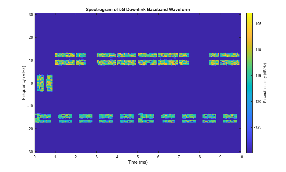
Plot the spectrogram of the waveform for the first antenna port.
samplerate = info.ResourceGrids(1).Info.SampleRate;
nfft = info.ResourceGrids(1).Info.Nfft;
figure;
spectrogram(waveform(:,1),ones(nfft,1),0,nfft,'centered',samplerate,'yaxis','MinThreshold',-130);
title('Spectrogram of 5G Downlink Baseband Waveform');
The waveform generator function returns the time-domain waveform and a structure info. The info structure contains the underlying resource element grid and a breakdown of the resources that all the PDSCH and PDCCH instances use in the waveform.
The ResourceGrids field is a structure array, which contains these fields.
The resource grid corresponding to each BWP.
The resource grid of the overall bandwidth containing the channels and signals in each BWP.
An info structure with information corresponding to each BWP. For example, display the information of the first BWP.
disp('Modulation information associated with BWP 1:')
disp(info.ResourceGrids(1).Info)
Modulation information associated with BWP 1:
                   Nfft: 4096
             SampleRate: 61440000
    CyclicPrefixLengths: [320 288 288 288 288 288 288 320 288 … ] (1×14 double)
          SymbolLengths: [4416 4384 4384 4384 4384 4384 4384 … ] (1×14 double)
              Windowing: 0
           SymbolPhases: [0 0 0 0 0 0 0 0 0 0 0 0 0 0]
         SymbolsPerSlot: 14
       SlotsPerSubframe: 1
          SlotsPerFrame: 10
                     k0: 0

The generated resource grid is a 3-D matrix. The different planes in the grid represent the antenna ports in increasing port number order.
See Also
Functions
Objects
nrWavegenBWPConfig|nrSCSCarrierConfig|nrULCarrierConfig|nrWavegenPDSCHConfig|nrWavegenSSBurstConfig|nrSearchSpaceConfig|nrWavegenPDCCHConfig|nrCORESETConfig|nrWavegenCSIRSConfig