NR Phase Noise Modeling and Compensation
This example demonstrates the impact of phase noise in a 5G OFDM system and shows how to use phase tracking reference signal (PT-RS) in compensating the common phase error (CPE). The example measures error vector magnitude (EVM) and bit error rate (BER) with and without CPE compensation.
Introduction
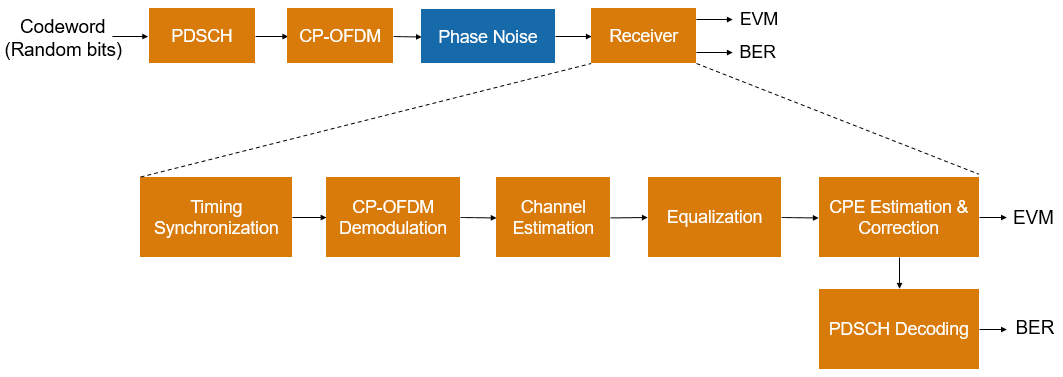
In 5G NR, 3GPP introduces a new reference signal, named phase tracking reference signal (PT-RS), to deal with oscillator noise. The noise incurred in the oscillators results in phase modulation of the information signal, leading to significant changes in the frequency spectrum and timing properties of the information signal. This phenomenon related to oscillators is called phase noise. Phase noise produced in local oscillators introduces a significant degradation at millimeter wave (mmWave) frequencies, depending on the power spectral density of phase noise. Phase noise leads to CPE and intercarrier interference (ICI). CPE leads to an identical rotation of a received symbol in each subcarrier. ICI leads to a loss of orthogonality between the subcarriers. Due to the distributed structure of PT-RS in frequency domain, the example primarily uses PT-RS to estimate and minimize the effect of CPE on system performance. The example applies phase noise on the waveform consisting of physical downlink shared channel (PDSCH) and shows the change in EVM and BER without and with CPE compensation. This figure shows the processing chain implemented in this example.
Phase Noise Modeling
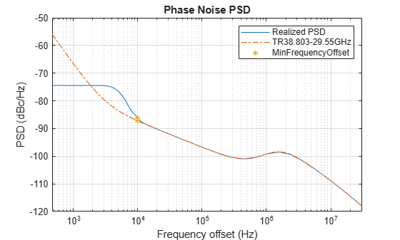
The oscillator power spectral density models the phase noise. This example uses a multipole zero model described in 3GPP TR 38.803: Radio Frequency (RF) and co-existence aspects, Section 6.1.10 to approximate the power spectral density of the oscillator. A System Object™ nrPhaseNoise models the phase noise power spectral density (PSD) profiles recommended in TR 38.803. Set the PoleZeroModel property to 'TR38.803-29.55GHz', 'TR38.803-45GHz' or 'TR38.803-70GHz' to use the parameter set for model operating at 29.55 GHz, 45 GHz or 70 GHz, respectively. Set the PoleZeroModel property to 'TR38.803-auto' to specify the model that is closest to the specified CarrierFrequency property value. Set the MinFrequencyOffset property to a smaller value to improve the match between the realized and recommended PSD, with a trade-off of increased simulation time.
The example uses a carrier with a subcarrier spacing of 60 kHz for a transmission bandwidth of 50 MHz.
% Configure carrier
carrier = nrCarrierConfig;
carrier.SubcarrierSpacing = 60;
carrier.CyclicPrefix = 'normal';
carrier.NSizeGrid = 66;

% Set the operating frequency
Fc = 30e9; % Hz

% Get the sample rate
ofdmInfo = nrOFDMInfo(carrier);
sr = ofdmInfo.SampleRate;

% Model phase noise
pnoise = nrPhaseNoise(CarrierFrequency=Fc, ...
    SampleRate=sr, ...
    MinFrequencyOffset=1e4,...
    RandomStream="mt19937ar");             % dBc/Hz, PoleZeroModel='TR38.803-auto'

% Visualize spectrum mask of phase noise
visualize(pnoise)
Configure PDSCH
The example configures PDSCH occupying the complete carrier with modulation scheme set to '64QAM' and number of layers set to 1. The example defaults to a single layer and a single codeword of random uncoded bits.
% Set PDSCH parameters
pdsch = nrPDSCHConfig;
pdsch.PRBSet = 0:carrier.NSizeGrid-1;
pdsch.SymbolAllocation = [0 14];
pdsch.Modulation = '64QAM';
pdsch.NumLayers = 1;
pdsch.MappingType = 'A';
pdsch.NID = 1;
pdsch.RNTI = 2;

% Set DM-RS parameters
pdsch.DMRS.DMRSConfigurationType = 1;
pdsch.DMRS.DMRSTypeAPosition = 2;
pdsch.DMRS.DMRSAdditionalPosition = 0;
pdsch.DMRS.DMRSLength = 1;
pdsch.DMRS.DMRSPortSet = [];
pdsch.DMRS.NumCDMGroupsWithoutData = 1;
pdsch.DMRS.NIDNSCID = 1;
pdsch.DMRS.NSCID = 0;

% Set PT-RS parameters
pdsch.EnablePTRS = 1;
pdsch.PTRS.TimeDensity = 1;
pdsch.PTRS.FrequencyDensity = 2;
pdsch.PTRS.REOffset = '00';
pdsch.PTRS.PTRSPortSet = [];
Generate Waveform
The waveform is generated for 2 frames and the field NumFrames of simParameters structure controls the number of frames of the waveform. The steps involved are:
Generate random codeword with the bit capacity of PDSCH
Get the PDSCH symbols for the random codeword and map them to grid
Generate and map DM-RS symbols to grid
Generate and map PT-RS symbols to grid
Perform OFDM modulation for the complete grid of all frames
% Number of frames to generate the waveform
simParameters = [];
simParameters.NumFrames = 2;

% Get the number of slots in the waveform and number of symbols in a slot
numSlots = carrier.SlotsPerFrame*simParameters.NumFrames;
nSlotSymb = carrier.SymbolsPerSlot;

% Initialize the grid for specified number of frames
txGrid = zeros(carrier.NSizeGrid*12,nSlotSymb*numSlots,pdsch.NumLayers);

% Processing loop
txbits = [];
rng('default')
for slotIdx = 0:numSlots - 1
    % Set slot number
    carrier.NSlot = slotIdx;

    % Get PDSCH indices and structural information
    [pdschInd,pdschIndicesInfo] = nrPDSCHIndices(carrier,pdsch);

    % Generate random codeword(s)
    numCW = pdsch.NumCodewords; % Number of codewords
    data = cell(1,numCW);
    for i = 1:numCW
        data{i} = randi([0 1],pdschIndicesInfo.G(i),1);
        txbits = [txbits; data{i}]; %#ok<AGROW>
    end

    % Get modulated symbols
    pdschSym = nrPDSCH(carrier,pdsch,data);

    % Get DM-RS symbols and indices
    dmrsSym = nrPDSCHDMRS(carrier,pdsch);
    dmrsInd = nrPDSCHDMRSIndices(carrier,pdsch);

    % Get PT-RS symbols and indices
    ptrsSym = nrPDSCHPTRS(carrier,pdsch);
    ptrsInd = nrPDSCHPTRSIndices(carrier,pdsch);

    % Resource element mapping to slot grid
    slotGrid = nrResourceGrid(carrier,pdsch.NumLayers);
    slotGrid(pdschInd) = pdschSym;
    slotGrid(dmrsInd) = dmrsSym;
    slotGrid(ptrsInd) = ptrsSym;

    % Generate txGrid for all frames by mapping slotGrid at respective
    % locations
    txGrid(:,slotIdx*nSlotSymb+1:(slotIdx+1)*(nSlotSymb),:) = slotGrid;
end

% Perform OFDM modulation
carrier.NSlot = 0; % Reset the slot number to 0 for OFDM modulation
txWaveform = nrOFDMModulate(carrier,txGrid);
Apply Phase Noise
Apply phase noise to the transmitted waveform. To clearly observe the impact of phase noise, the example does not apply any thermal noise or channel model in addition to phase noise. The example applies the same phase noise to all the layers.
rxWaveform = pnoise(txWaveform);
Receiver
Before returning the equalized PDSCH symbols and decoded bits, the receiver performs these steps:
Timing synchronization
OFDM demodulation
Channel estimation
Equalization
CPE estimation and correction
PDSCH decoding
For the CPE estimation and correction step, the receiver uses the logical field CompensateCPE of the simParameters structure. Because the example does not use a propagation channel, the steps of timing synchronization, channel estimation, and equalization are not strictly necessary. However, these steps help investigate the phase noise effects if you introduce a channel.
The example shows the equalized constellation symbols, EVM, and bit error rate, with and without CPE compensation.
Case 1: Without CPE Compensation
To disable the CPE compensation, set the field CompensateCPE of simParameters structure to 0.
simParameters.CompensateCPE = 0;
[eqSymbols,rxbits] = practicalReceiver(carrier,pdsch,simParameters,rxWaveform);
refSymbols = getConstellationPoints(pdsch);
% Display the constellation diagram
figure
plot(eqSymbols,'.')
hold on
plot(refSymbols,'+')
title('Equalized Symbols Constellation Without CPE Compensation')
grid on
xlabel('In-Phase')
ylabel('Quadrature')
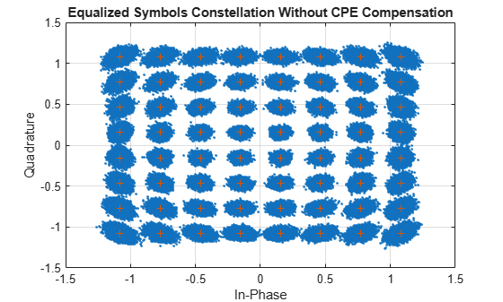
% Display RMS EVM
evm = comm.EVM('ReferenceSignalSource','Estimated from reference constellation','ReferenceConstellation',refSymbols);
fprintf('RMS EVM (in percent) for equalized symbols without CPE compensation: %f%% \n',evm(eqSymbols))
RMS EVM (in percent) for equalized symbols without CPE compensation: 4.637565%
% Display bit error rate
errorRate = nnz(rxbits-txbits)/numel(txbits);
fprintf('Bit error rate without CPE compensation: %f \n',errorRate)
Bit error rate without CPE compensation: 0.000019
Case 2: With CPE Compensation
To enable the CPE compensation, set the field CompensateCPE of simParameters structure to 1. Use PT-RS to estimate the CPE at all the OFDM symbol locations in a slot. Correct the CPE in the OFDM symbol locations within the range of PT-RS OFDM symbols.
simParameters.CompensateCPE = 1;
[eqSymbolsCPE,rxbitsCPE] = practicalReceiver(carrier,pdsch,simParameters,rxWaveform);
% Display the constellation diagram
figure
plot(eqSymbolsCPE,'.')
hold on
plot(refSymbols,'+')
title('Equalized Symbols Constellation With CPE Compensation')
grid on
xlabel('In-Phase')
ylabel('Quadrature')
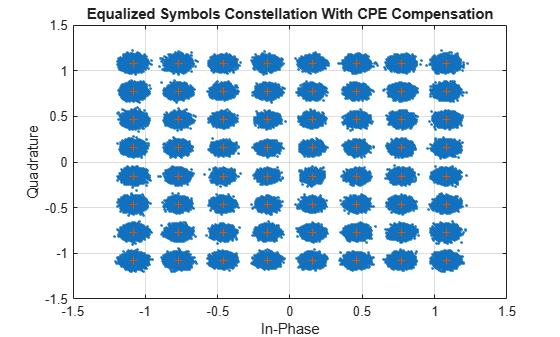
% Display RMS EVM
fprintf('RMS EVM (in percent) for equalized symbols with CPE compensation: %f%% \n',evm(eqSymbolsCPE))
RMS EVM (in percent) for equalized symbols with CPE compensation: 3.982680%
% Display bit error rate
errorRateCPE = nnz(rxbitsCPE-txbits)/numel(txbits);
fprintf('Bit error rate with CPE compensation: %f \n',errorRateCPE)
Bit error rate with CPE compensation: 0.000000
Further Exploration
To visualize the impact of phase noise, change the carrier frequency, subcarrier spacing, number of resource blocks, modulation scheme, and the number of frames.
To analyze the effect of CPE compensation with different configurations, change the time and frequency density of PT-RS.
Visualize the impacts of phase noise by including thermal noise and channel models.
Summary
This example demonstrates the impact of phase noise and shows how to estimate and correct CPE with PT-RS. The example also shows that CPE compensation reduces the EVM and improves bit error rate. The displayed constellation plot shows huge ICI in mmWave frequencies, indicating that ICI compensation needs to be performed in addition to CPE compensation.
Local Functions
function [eqSymbols,rxbits] = practicalReceiver(carrier,pdsch,params,rxWaveform)
% Returns equalized modulated symbols after performing the timing
% estimation, OFDM demodulation, channel estimation, MMSE equalization,
% CPE estimation and correction, and PDSCH decoding.

    % Get the current slot number, number of slots, number of symbols
    % per slot, and total number of symbols
    nSlot = carrier.NSlot;
    numSlots = carrier.SlotsPerFrame*params.NumFrames;
    nSlotSymb = carrier.SymbolsPerSlot;
    numTotalSymbols = numSlots*nSlotSymb;

    % Get reference grid with DM-RS symbols
    dmrsSymCell = cell(1,numSlots);
    dmrsIndCell = cell(1,numSlots);
    refGrid = zeros(carrier.NSizeGrid*12,numTotalSymbols,pdsch.NumLayers);
    for NSlot = 0:numSlots-1
        carrier.NSlot = NSlot;
        slotGrid = nrResourceGrid(carrier,pdsch.NumLayers);
        dmrsSymCell{NSlot+1} = nrPDSCHDMRS(carrier,pdsch);
        dmrsIndCell{NSlot+1} = nrPDSCHDMRSIndices(carrier,pdsch);
        slotGrid(dmrsIndCell{NSlot+1}) = dmrsSymCell{NSlot+1};
        refGrid(:,NSlot*nSlotSymb+1:(NSlot+1)*(nSlotSymb),:) = slotGrid;
    end

    % Perform timing estimation and correction
    carrier.NSlot = nSlot;
    offset = nrTimingEstimate(carrier,rxWaveform,refGrid);
    waveformSync = rxWaveform(1+offset:end,:);

    % Perform OFDM demodulation on the received data to recreate the
    % resource grid, including padding in the event that practical
    % synchronization results in an incomplete slots being demodulated
    rxGrid = nrOFDMDemodulate(carrier,waveformSync);
    [K,L,R] = size(rxGrid);
    if (L < numTotalSymbols)
        rxGrid = cat(2,rxGrid,zeros(K,numTotalSymbols-L,R));
    end

    % Declare storage variables
    eqSymbols = [];  % equalized symbols for constellation plot
    rxbits = [];

    for NSlot = 0:numSlots-1
        % Extract grid for current slot
        currentGrid = rxGrid(:,NSlot*nSlotSymb+(1:nSlotSymb),:);

        % Get the PDSCH resources
        carrier.NSlot = NSlot;
        dmrsSymbols = dmrsSymCell{NSlot+1};
        dmrsIndices = dmrsIndCell{NSlot+1};
        pdschIndices = nrPDSCHIndices(carrier,pdsch);

        % Channel estimation
        [estChannelGrid,noiseEst] = nrChannelEstimate(currentGrid,dmrsIndices,dmrsSymbols,"CDMLengths",pdsch.DMRS.CDMLengths);

        % Get PDSCH resource elements from the received grid
        [pdschRx,pdschHest] = nrExtractResources(pdschIndices,currentGrid,estChannelGrid);

        % Equalization
        pdschEq = nrEqualizeMMSE(pdschRx,pdschHest,noiseEst);

        % Common phase error (CPE) estimation and correction
        if params.CompensateCPE
            pdschEq = hCompensateCPE(carrier,pdsch,pdschEq,currentGrid,estChannelGrid,noiseEst);
        end

        % Store the equalized symbols and output them for all the slots
        eqSymbols = [eqSymbols; pdschEq]; %#ok<AGROW>

        % Decode the PDSCH symbols and get the hard bits
        eqbits = nrPDSCHDecode(carrier,pdsch,pdschEq);
        for i = 1:numel(eqbits)
            rxbits = [rxbits; double(eqbits{i}<0)]; %#ok<AGROW>
        end

    end

end

function sym = getConstellationPoints(pdsch)
%getConstellationPoints Constellation points
%   SYM = getConstellationPoints(PDSCH) returns the constellation points
%   SYM based on modulation schemes provided in PDSCH configuration object.

    sym = [];
    modulation = string(pdsch.Modulation);  % Convert modulation scheme to string type
    ncw = pdsch.NumCodewords;               % Number of codewords
    if ncw == 2 && isscalar(modulation)
        modulation(end+1) = modulation(1);
    end
    % Get the constellation points
    for cwIndex = 1:ncw
        qm = strcmpi(modulation(cwIndex),{'QPSK','16QAM','64QAM','256QAM'})*[2 4 6 8]';
        sym = [sym; nrSymbolModulate(int2bit((0:2^qm-1)',qm),modulation(cwIndex))]; %#ok<AGROW>
    end

end