Modeling Wire Antenna and Arrays
This example shows how to model V-dipole wire antennas and arrays using the wire basis function wireStack. This workflow eliminates the wire to strip approximation or the strip basis function you need to perform when converting strip structures to wire antennas. You can also use this workflow to model all the antenna elements from the dipole and loop antenna catalog families.
Create Strip Model V-Dipole Antenna
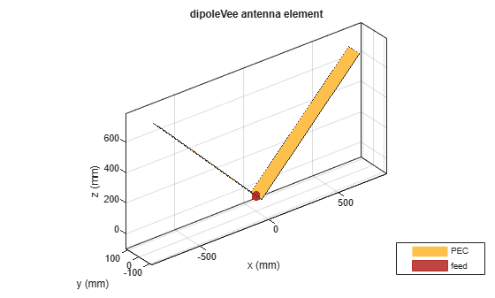
Create and display a dipoleVee antenna object. The default V-dipole resonates close to 75 MHz.
antStrip = dipoleVee;
show(antStrip)
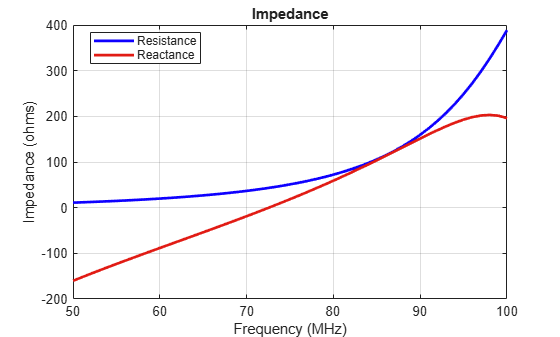
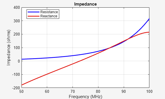
Calculate the impedance of the V-dipole antenna. The impedance plot shows that the V-dipole antenna resonates at 73 MHz.
freq = linspace(50e6,100e6,51);
impedance(antStrip,freq)
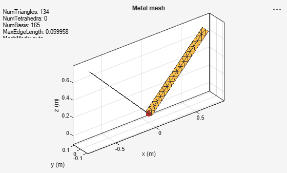
Display the antenna mesh plot. The antenna mesh plot shows that the strip surface is divided into triangles.
figure
mesh(antStrip)
Create Wire Model for V-Dipole Antenna
A V-dipole antenna is typically constructed using wires. Use the wireStack function to convert the strip model to a wire model. You cannot change the geometric properties of the antenna. However, you can set the FeedLocation, FeedVoltage, Tilt, and TiltAxis properties. To update the geometrical properties such as ArmLength and Width, you must convert the wire model back to the strip model.
antwire = wireStack(antStrip)
antwire =
  wireStack with properties:

            Name: 'V-dipole'
    FeedLocation: [-0.1250 0 0.1250]
     FeedVoltage: 1
       FeedPhase: 0
            Tilt: 0
        TiltAxis: [1 0 0]
As seen from the impedance plot, the behavior of the wire antenna is similar to the strip antenna.
impedance(antwire,freq)
Plot the mesh of the wire model of the V-dipole antenna.
figure
mesh(antwire)
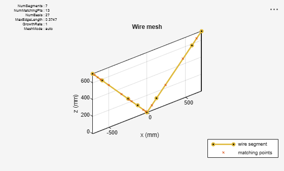
The meshes of the strip and the wire models of the V-dipole antenna are different. The mesh of the wire V-dipole antenna is based on the thin-wire approximation, that is, the wire is discretized into one-dimensional wire segments on which the current is approximated as a polynomial of order N. The currents at each segment are obtained by solving a set of N+1 equations per segment, two equations at the segment edges, and N-1 equations at matching points dispensed along the segment. The segments and matching points are displayed in the mesh plot to give a complete picture of the discretization choices made to solve the structure.
Create Array of Wire Antennas
To create an array of wire antennas, first create an array of the catalog element. This workflow applies to linear and conformal arrays.
Create and display a three-element V-dipole linear antenna array.
l = linearArray(Element=antStrip, NumElements=3);
arr = wireStack(l);
show(arr)
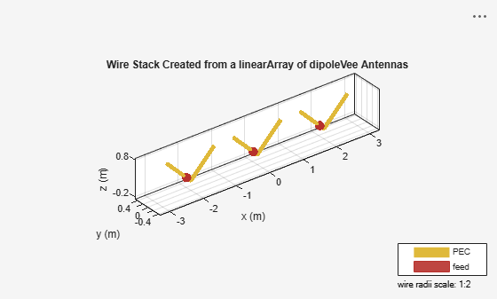
The feed point of the wire V-dipole is offset by a small amount from the antenna origin. This is the outcome of an implementation-based requirement that the feed be placed on a straight portion of the wire. The offset is roughly 7-wire radii.
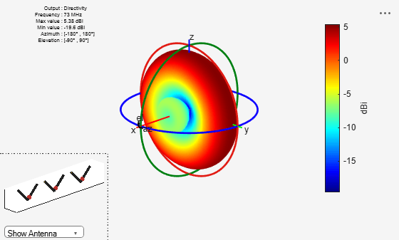
All the analysis supported for catalog elements are supported for wire arrays. Calculate the radiation pattern of the three-element V-dipole linear antenna array.
pattern(arr,73e6)