Main Content

Motorcycle Body Longitudinal In-Plane

Longitudinal in-plane motorcycle vehicle motion

Since R2021b

  • Motorcycle Body Longitudinal In-Plane block

Libraries:
Powertrain Blockset / Vehicle Dynamics
Vehicle Dynamics Blockset / Vehicle Body

Description

The Motorcycle Body Longitudinal In-Plane block implements a longitudinal in-plane motorcycle body model to calculate longitudinal, vertical, and pitch motion. The block accounts for:

  • Mass of the frame, rear arm, front upper fork, front lower fork, front wheel, and rear wheel

  • In-plane dynamic effects of the frame, front lower fork, front wheel, rear wheel, rear suspension, front suspension, rear wheel damper, rear arm, and chain

  • External forces, external moments, and aerodynamic drag

  • Road incline

  • Weight distribution between the axles due to acceleration

Consider using this block to represent motorcycle motion in powertrain and fuel economy studies, for example, in studies with heavy breaking or acceleration or road profiles that contain larger vertical changes.

The block uses rigid-body vehicle motion, suspension system forces, and wind and drag forces to calculate the forces on the motorcycle frames. The block then determines the position and velocity of motorcycle at the front and rear contact patches.

Layout

To determine the rigid-body motorcycle motion, the block uses right-handed (RH) Cartesian reference frames systems attached to the motorcycle. i, j, and k are orthogonal unit vectors attached to the frames.

Motorcycle body diagram

FrameVariable in FigureDescription
Road

x, z

Road-fixed coordinate system. x is along road grade, and z points downward.

Motorcycle main frame

  • iFrm – Forward along vector given by θfrm

  • kFrm – Downward

  • jFrm – Orthogonal to motorcycle plane

OFrm

Main frame origin

GFrm

Center of mass (CM) of the main frame with respect to OFrm, along iFrm and kFrm, respectively

GRdr

CM of the rider with respect to OFrm, along iFrm and kFrm, respectively

ϴfrm

Main frame rotation about jFrm

Upper fork

  • iFrkUp – Forward along vector given by θfrm

  • kFrkUp – Downward

  • jFrkUp – Orthogonal to motorcycle plane

OFrkUp

Upper fork origin

GFrkUp

CM of the upper fork with respect to OFrkUp, along iFrkUp and kFrkUp, respectively

Lower fork

  • iFrkLw – Forward along vector given by θfrm

  • kFrkLw – Downward

  • jFrkLw – Orthogonal to motorcycle plane

OFrkLw

Lower fork origin

GFrkLw

CM of the lower fork with respect to OFrkLw, along iFrkLw and kFrkLw, respectively

Rear arm

  • iArmRr – Forward along vector given by θra

  • kArmRr – Downward

  • jArmRr – Orthogonal to motorcycle plane

OArmRr

Rear arm origin

GArmRr

CM of the rear arm with respect to OArmRr, along iArmRr and kArmRr, respectively

ϴra

Rear arm rotation about jArmRr

Front wheel contact patch

  • iCpF – Forward along vector given by road-fixed x- axis

  • kCpF – Downward along vector given by road-fixed z- axis

  • jCpF – Orthogonal to motorcycle plane

OCpF

Front wheel contact patch origin

Rear wheel contact patch

  • iCpR – Forward along vector given by road-fixed x- axis

  • kCpR – Downward along vector given by road-fixed z- axis

  • jCpR – Orthogonal to motorcycle plane

OCpR

Rear wheel contact patch origin

Use the parameters in this table to specify the geometric layout of your motorcycle.

Parameter Variable in Figure

Initial conditions

Position

Rear contact patch longitudinal coordinate, CpRrX0

OCpR with respect to road-fixed coordinate system, along x

Rear contact patch vertical coordinate, CpRrZ0

OCpR with respect to road-fixed coordinate system, along z

Pitch angle of rear arm, ArmRrAng0

θra

Pitch angle of main frame, FrmAng0

θFrm

Fork length, FrkFrL0

df

Frame

Center of mass location, FrmCmPxz

GFrm with respect to OFrm, along iFrm and kFrm, respectively

Length, FrmLen

FrmLen

Rider

Center of mass location, RdrCmPxz

GRdr with respect to OFrm, along iFrm and kFrm, respectively

Front Fork

Upper

Position, FrkUpCmPxz

GFrkUp with respect to OFrkUp, along iFrkUp and kFrkUp, respectively

Offset, FrkOfs

FrkOfs
Lower

Position, FrkLwCmPxz

GFrkLw with respect to OFrkLw, along iFrkLw and kFrkLw, respectively

Rear Arm

Position, ArmRrCmPxz

GArmRr with respect to OArmRr, along iArmRr and kArmRr, respectively

Length, ArmRrLen

ArmRrLen

Wheels

Front

Radius, WhlFrR

WhlFrR
Rear

Radius, WhlRrR

WhlRrR

Suspension

Front

Equilibrium length, FrkLwL0

df
Rear

Equilibrium angle, ShkRrAng0

θFrm

Input Signals

You can use these block parameters to create additional input ports. This table summarizes the settings.

Input Signals Pane Parameter

Input PortDescription
External forcesFExt

External longitudinal and vertical forces applied at equivalent rider and motorcycle center of mass (CM).

External moments

MExt

External moment about equivalent rider and motorcycle CM, for example, moment due to rider physical motion.

External front wheel momentMWhlF

External moment at the front wheel GWhlFr, for example, wheel motors and external intermittent friction-related disturbances.

External rear wheel moment

MWhlR

External moment at the rear wheel GWhlRr, for example, wheel motors and external intermittent friction-related disturbances.

Grade angle

Grade

Road grade angle.

Wind velocity

WindXYZ

Wind speed.

Ambient temperature

Temp

Ambient air temperature. Consider this option if you want to vary the temperature during run-time.

Suspension System

Use the Suspension type parameter to specify the type of suspension.

Setting

Description

Simple

Block models the suspension force and moment as a spring-damper system:

  • Suspension force at the upper fork

  • Suspension moment at the rear arm

User-defined

Input the suspension force and moment:

  • FSuspF – Suspension force at the upper fork

  • MSuspR – Suspension moment at the rear arm

Wind and Drag Forces

The block subtracts the wind speeds from the vehicle velocity components to obtain a net relative airspeed. To calculate the drag force and moments acting on the motorcycle, the block uses the net relative airspeed.

Power Accounting

The block accounts for the power transferred, not transferred, and stored.

Bus Signal Description

PwrInfo

PwrTrnsfrd — Power transferred between blocks

  • Positive signals indicate flow into block

  • Negative signals indicate flow out of block

PwrFxExt

Mechanical power from longitudinal external force

PwrFzExt

Mechanical power from vertical external force

PwrMyExt

Mechanical power from external pitch moment

PwrNotTrnsfrd — Power crossing the block boundary, but not transferred

  • Positive signals indicate an input

  • Negative signals indicate a loss

PwrFxDrag

Mechanical power loss from longitudinal drag force

PwrFzDrag

Mechanical power loss from vertical lift

PwrMyDrag

Mechanical power loss from pitch moment drag

PwrStored — Stored energy rate of change

  • Positive signals indicate an increase

  • Negative signals indicate a decrease

PwrStoredGrvty

Rate change in gravitational potential energy

PwrStoredxdot

Rate of change of longitudinal kinetic energy

PwrStoredzdot

Rate of change of vertical kinetic energy

PwrStoredq

Rate of change of rotational pitch kinetic energy

PwrStoredFsFzSprng

Stored spring energy from front suspension

PwrStoredFsRzSprng

Stored spring energy from rear suspension
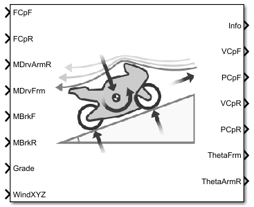
Ports

Input

expand all

Longitudinal and vertical forces at front wheel contact patch OCpF, along iCpF and kCpF, in N. Signal vector dimensions are [1x2] or [2x1].

Longitudinal and vertical forces at rear wheel contact patch OCpR, along iCpR and kCpR, in N. Signal vector dimensions are [1x2] or [2x1].

Drive chain moment at rear arm OArmRr, about jArmRr, in N·m.

Drive chain moment at the frame OFrm, about jFrm, in N·m.

External longitudinal and vertical forces applied at equivalent rider and motorcycle center of mass (CM), along iFrm and kFrm, in N. Signal vector dimensions are [1x2] or [2x1].

Dependencies

To create this port, select External forces.

External moment about equivalent rider and motorcycle CM, jFrm, for example, moment due to rider physical motion, in N·m.

Dependencies

To create this port, select External moments.

Brake moment at the front wheel GWhlFr, about jWhlFr, in N·m.

Brake moment at the rear wheel GWhlRr, about jWhlRr, in N·m.

External moment at the front wheel GWhlFr, in N·m.

Dependencies

To create this port, select External front wheel moment.

External moment at the rear wheel GWhlRr, in N·m.

Dependencies

To create this port, select External rear wheel moment.

External suspension force at upper fork OFrkUp, along kFrkUp, in N.

Dependencies

To create this port, set Suspension type to User-defined.

External suspension force at upper fork OArmRr, about jArmRr, in N·m.

Dependencies

To create this port, set Suspension type to User-defined.

Road grade angle, γ, in deg.

Dependencies

To create this port, select Grade angle.

Wind speed, WX, WY, WZ along earth-fixed X-, Y-, and Z-axes, in m/s. Signal vector dimensions are [1x3] or [3x1].

Dependencies

To create this port, select Wind velocity.

Ambient air temperature, Tair, in K. Considering this option if you want to vary the temperature during run-time.

Dependencies

To create this port, select Ambient temperature.

Output

expand all

Bus signal containing these block calculations.

Signal

Signal

Units

GeomPosOrgInert

Main frame position along the earth-fixed axes

m
PosFwBdy

Front wheel center position relative to initial vehicle-fixed wheel position, along the vehicle Z-down X-, Y-, and Z-axes

m
PosRwBdy

Rear wheel center position relative to initial vehicle-fixed wheel position, along the vehicle Z-down X-, Y-, and Z-axes

m
AngOrgInert

Main frame rotation about the earth-fixed axes

rad
FrameInertCgDispXVehicle CM displacement along the earth-fixed X-axism
Y

Vehicle CM displacement along the earth-fixed Y-axis

m
Z

Vehicle CM displacement along the earth-fixed Z-axis

m
VelXdot

Vehicle CM velocity along the earth-fixed X-axis

m/s
Ydot

Vehicle CM velocity along the earth-fixed Y-axis

m/s
Zdot

Vehicle CM velocity along the earth-fixed Z-axis

m/s
Angphi

Rotation of the vehicle-fixed frame about the earth-fixed X-axis (roll)

rad
theta

Rotation of the vehicle-fixed frame about the earth-fixed Y-axis (pitch)

rad
psi

Rotation of the vehicle-fixed frame about the earth-fixed Z-axis (yaw)

rad
BdyFrmCgDispx

Vehicle CM position along the road-fixed x-axis

m
y

Vehicle CM position along the road-fixed y-axis

m
zVehicle CM position along the road-fixed z-axism
VelxdotVehicle CM velocity along the road-fixed x-axism/s
ydotVehicle CM velocity along the road-fixed y-axism/s
zdotVehicle CM velocity along the road-fixed z-axism/s
AngVelpVehicle angular velocity about the road-fixed x-axis (roll rate)rad/s
qVehicle angular velocity about the road-fixed y-axis (pitch rate)rad/s
rVehicle angular velocity about the road-fixed z-axis (yaw rate)rad/s
AccaxVehicle CM acceleration along the road-fixed x-axism/s2
ayVehicle CM acceleration along the road-fixed y-axism/s2
azVehicle CM acceleration along the road-fixed z-axism/s2
xddotVehicle CM acceleration along the road-fixed x-axism/s2
yddotVehicle CM acceleration along the road-fixed y-axism/s2
zddotVehicle CM acceleration along the road-fixed z-axism/s2
AngAccpdotVehicle angular acceleration about the road-fixed x-axisrad/s2
qdotVehicle angular acceleration about the road-fixed y-axisrad/s2
rdotVehicle angular acceleration about the road-fixed z-axisrad/s2
ForcesExtFxExternal force on vehicle CM along the road-fixed x-axisN
FyExternal force on vehicle CM along the road-fixed x-axisN
FzExternal force on vehicle CM along the road-fixed x-axisN
DragFxDrag force on vehicle CM along the road-fixed x-axisN
FyDrag force on vehicle CM along the road-fixed y-axisN
FzDrag force on vehicle CM along the road-fixed z-axisN
GrvtyFxGravity force on vehicle CM along the road-fixed x-axisN
FyGravity force on vehicle CM along the road-fixed y-axisN
FzGravity force on vehicle CM along the road-fixed z-axisN
MomentsDragMxDrag moment on vehicle CM about the road-fixed x-axisN·m
MyDrag moment on vehicle CM about the road-fixed z-axisN·m
MzDrag moment on vehicle CM about the road-fixed z-axisN·m
ExtMxExternal moment on vehicle CG about the road-fixed x-axisN·m
MyExternal moment on vehicle CG about the road-fixed y-axisN·m
MzExternal moment on vehicle CG about the road-fixed z-axisN·m
PwrPwrExtApplied external powerW
DragPower loss due to dragW
PwrInfo

Pwr

Trnsfrd

PwrFxExt

Mechanical power from longitudinal external force

W
PwrFzExt

Mechanical power from vertical external force

W
PwrMyExtMechanical power from external pitch momentW

PwrNot

Trnsfrd

PwrFxDrag

Mechanical power loss from longitudinal drag force

W
PwrFzDrag

Mechanical power loss from vertical lift force

W
PwrMyDrag

Mechanical power loss from pitch moment drag

W
PwrStoredPwrStoredGrvtyRate change in gravitational potential energyW
PwrStoredxdotRate of change of longitudinal kinetic energyW
PwrStoredzdotRate of change of vertical kinetic energyW
PwrStoredqRate of change of rotational pitch kinetic energyW
GenrlVelxdotVehicle CM velocity along the road-fixed x-axism/s
zdotVehicle CM velocity along the road-fixed z-axism/s
AngthetafrmPitch angle of main framerad
AngVelthetafrmdotMain frame rotational velocity rad/s
AngAccthetafrmddotMain frame rotational acceleration rad/s2
WhlGenrlFrntCpDispx

Front wheel contact patch position along the road-fixed x-axis

m
z

Front wheel contact patch position along the road-fixed z-axis

m
Velxdot

Front wheel contact patch velocity along the road-fixed x-axis

m/s
zdot

Front wheel contact patch velocity along the road-fixed z-axis

m/s
Accxddot

Front wheel contact patch acceleration along the road-fixed x-axis

m/s2
zddot

Front wheel contact patch acceleration along the road-fixed z-axis

m/s2
AxlVelxdot

Front wheel axle velocity along the road-fixed x-axis

m/s
zdot

Front wheel axle velocity along the road-fixed z-axis

m/s
RearCpDispx

Rear wheel contact patch position along the road-fixed x-axis

m
z

Rear wheel contact patch position along the road-fixed z-axis

m
Velxdot

Rear wheel contact patch velocity along the road-fixed x-axis

m/s
zdot

Rear wheel contact patch velocity along the road-fixed z-axis

m/s
Accxddot

Rear wheel contact patch acceleration along the road-fixed x-axis

m/s2
zddot

Rear wheel contact patch acceleration along the road-fixed z-axis

m/s2
AxlVelxdot

Rear wheel axle velocity along the road-fixed x-axis

m/s
zdot

Rear wheel axle velocity along the road-fixed z-axis

m/s
RearArmGenrlVelxdot

Rear arm velocity along the road-fixed x-axis

m/s
zdot

Rear arm velocity along the road-fixed z-axis

m/s
AngthetaraPitch angle of rear armrad
AngVelthetaradotRear arm rotational velocity rad/s
AngAccthetaraddotRear arm rotational acceleration rad/s2
ForkGenrlUprVelxdot

Upper fork velocity along the road-fixed x-axis

m/s
zdot

Upper fork velocity along the road-fixed z-axis

m/s
LwrDispdfFork lengthm
Velxdot

Lower fork velocity along the road-fixed x-axis

m/s
zdot

Lower fork velocity along the road-fixed z-axis

m/s
dfdotFork length velocitym/s
AccdfddotFork length accelerationm/s2
SuspGenrlRearMomentsMthetafrm

Rear suspension moment at frame

N·m
FrntForcesFdf

Suspensive force at upper fork

N

Longitudinal, lateral, and vertical velocity at front wheel contact patch OCpF, along iCpF and kCpF, in m/s. Signal vector dimensions are [1x3] or [3x1]. The lateral component is set to 0.

Longitudinal, lateral, and vertical position at front wheel contact patch OCpF, along iCpF and kCpF, in m. Signal vector dimensions are [1x3] or [3x1]. The lateral component is set to 0.

Longitudinal, lateral, and vertical velocity at rear wheel contact patch OCpR, along iCpR and kCpR, in m/s. Signal vector dimensions are [1x3] or [3x1]. The lateral component is set to 0.

Longitudinal, lateral, and vertical position at rear wheel contact patch OCpR, along iCpR, and kCpR, in m. Signal vector dimensions are [1x3] or [3x1]. The lateral component is set to 0.

Main frame pitch angle, ϴfrm, in rad.

Rear arm pitch angle, ϴra, in rad.

Parameters

expand all

Options

Use the Suspension type parameter to specify the type of suspension.

Setting

Description

Simple

Block models the suspension force and moment as a spring-damper system:

  • Suspension force at the upper fork

  • Suspension moment at the rear arm

User-defined

Input the suspension force and moment:

  • FSuspF – Suspension force at the upper fork

  • MSuspR – Suspension moment at the rear arm

Input signals

Specify to create input port FExt.

Specify to create input port MExt.

Specify to create input port MWhlF. Consider using this port to input external moments such as wheel motors and external intermittent friction-related disturbances.

Specify to create input port MWhlR. Consider using this port to input external moments such as wheel motors and external intermittent friction-related disturbances.

Specify to create input port Grade.

Specify to create input port WindXYZ.

Specify to create input port Temp.

Layout

Motorcycle body diagram

Use the parameters in this table to specify the geometric layout of your motorcycle.

Parameter Variable in Figure

Initial conditions

Position

Rear contact patch longitudinal coordinate, CpRrX0

OCpR with respect to road-fixed coordinate system, along x

Rear contact patch vertical coordinate, CpRrZ0

OCpR with respect to road-fixed coordinate system, along z

Pitch angle of rear arm, ArmRrAng0

θra

Pitch angle of main frame, FrmAng0

θFrm

Fork length, FrkFrL0

df

Frame

Center of mass location, FrmCmPxz

GFrm with respect to OFrm, along iFrm and kFrm, respectively

Length, FrmLen

FrmLen

Rider

Center of mass location, RdrCmPxz

GRdr with respect to OFrm, along iFrm and kFrm, respectively

Front Fork

Upper

Position, FrkUpCmPxz

GFrkUp with respect to OFrkUp, along iFrkUp and kFrkUp, respectively

Offset, FrkOfs

FrkOfs
Lower

Position, FrkLwCmPxz

GFrkLw with respect to OFrkLw, along iFrkLw and kFrkLw, respectively

Rear Arm

Position, ArmRrCmPxz

GArmRr with respect to OArmRr, along iArmRr and kArmRr, respectively

Length, ArmRrLen

ArmRrLen

Wheels

Front

Radius, WhlFrR

WhlFrR
Rear

Radius, WhlRrR

WhlRrR

Suspension

Front

Equilibrium length, FrkLwL0

df
Rear

Equilibrium angle, ShkRrAng0

θFrm

Frame

Center of mass location of the frame, GFrm. Specified as a vector with respect to OFrm, along iFrm and kFrm, respectively.

Frame mass, FrmMass, in kg.

Mass moment of inertia, FrmIyy, in kg·m2.

Length of the frame, FrmLen, in m.

Rider

Center of mass location of the rider, GRdr. Specified as a vector with respect to OFrm, along iFrm and kFrm, respectively.

Rider mass, RdrMass, in kg.

Rider mass moment of inertia, RdrIyy, in kg·m2.

Front Fork – Upper

Center of mass location of the upper fork, GFrkUp. Specified as a vector with respect to OFrkUp, along iFrkUp and kFrkUp, respectively.

Upper fork mass, FrkUpMass, in kg.

Upper fork mass moment of inertia, FrkUpIyy, in kg·m2.

Upper fork offset, FrkOfs, in m.

Front Fork – Lower

Center of mass location of the lower fork, GFrkLw. Specified as a vector with respect to OFrkLw, along iFrkLw and kFrkLw, respectively.

Lower fork mass, FrkLwMass, in kg.

Lower fork mass moment of inertia, FrkLwIyy, in kg·m2.

Rear Arm

Center of mass location of the rear arm, GArmRr. Specified as a vector with respect to OArmRr, along iArmRr and kArmRr, respectively.

Rear arm mass, ArmRrMass, in kg.

Rear arm mass moment of inertia, ArmRrIyy, in kg·m2.

Rear arm length, ArmRrLen, in m.

Wheels – Front

Front wheel mass, WhlFrMass, in kg.

Front wheel radius, WhlFrR, in m.

Wheels – Rear

Rear wheel mass, WhlRrMass, in kg.

Rear wheel radius, WhlRrR, in m.

Suspension – Front

Front suspension stiffness at OFrkUp, along kFrkUp, in N/m.

Front suspension damping, at OFrkUp, along kFrkUp, in N·s/m.

Front suspension equilibrium length, df, in m.

Suspension – Rear

Rear arm suspension stiffness at OArmRr, about jArmRr, in N/rad.

Rear arm suspension damping at OArmRr, about jArmRr, in N·s/rad.

Rear suspension equilibrium angle, θFrm, in rad.

Aerodynamic

Effective vehicle cross-sectional area, Af to calculate the aerodynamic drag force on the vehicle, in m2.

Air drag coefficient, Cd, dimensionless.

Air lift coefficient, Cl, dimensionless.

Longitudinal drag pitch moment coefficient, Cpm, dimensionless.

Pitch moment length, Lcpm, in m.

Environment

Gravitational acceleration, g, in m/s2.

Environmental air absolute pressure, Pabs, in Pa.

Ambient air temperature, Tair, in K.

Dependencies

To enable this parameter, clear Ambient temperature.

Initial conditions

Position

Rear contact patch longitudinal coordinate, OCpR, with respect to road-fixed coordinate system, along x, in m.

Rear contact patch vertical coordinate, OCpR, with respect to road-fixed coordinate system, along z, in m.

Pitch angle of rear arm, θra, in rad.

Pitch angle of main frame, θFrm, in rad.

Fork length, df, in m.

Velocity

Rear contact patch longitudinal coordinate, O˙CpR, with respect to road-fixed coordinate system, along x, in m/s.

Vertical velocity of rear contact patch, O˙CpR, with respect to road-fixed coordinate system, along z, in m/s.

Pitch rate of rear arm, θ˙ra, in rad/s.

Pitch rate of main frame, θ˙Frm, in rad/s.

Lower fork deformation velocity, d˙f, in m/s.

Coordinate Offsets

Vehicle main frame offset along the earth-fixed X-axis, in m.

Vehicle main frame offset along the earth-fixed Y-axis, in m.

Vehicle main frame offset along the earth-fixed Z-axis, in m.

Vehicle main frame offset about the earth-fixed X-axis, in rad.

Vehicle main frame offset about the earth-fixed Y-axis, in rad.

Vehicle main frame offset about the earth-fixed Z-axis, in rad.

References

[1] Giner, David Moreno. “Symbolic-Numeric Tools for the Analysis of Motorcycle Dynamics. Development of a Virtual Rider for Motorcycles Based on Model Predictive Control.” PhD diss., Universidad Miguel Hernández de Elche, 2016.

Extended Capabilities

C/C++ Code Generation
Generate C and C++ code using Simulink® Coder™.

Version History

Introduced in R2021b