Capture and Stitch Together Images from Multiple Cameras on NVIDIA Jetson
This example shows how to acquire images from two cameras connected to an NVIDIA® Jetson™ board and stitch them together to generate a composite image.
In this example, you:
Configure a Simulink® model to acquire images from two cameras connected to an NVIDIA Jetson embedded target.
Implement a correlation-based image stitching algorithm.
Configure the model for GPU code generation, generate a CUDA® executable for the Simulink model, and deploy it on the NVIDIA Jetson embedded target.
Prerequisites
Target Board Requirements
NVIDIA Jetson embedded platform.
NVIDIA CUDA toolkit.
Simple DirectMedia Layer (SDL) and GStreamer libraries.
Environment variables on the target for the compilers and libraries. For more information, see Prerequisites for Generating Code for NVIDIA Boards.
Additionally, if you cannot connect the target board to a local network, this example requires an Ethernet crossover cable to connect the target board and host PC.
Development Host Requirements
NVIDIA CUDA toolkit on the host and environment variables for the compilers and libraries. For more information, see Third-Party Hardware (GPU Coder) and Setting Up the Prerequisite Products (GPU Coder).
Connect the Host Computer to NVIDIA Hardware
MATLAB® Coder™ Support Package for NVIDIA Jetson and NVIDIA DRIVE Platforms uses an SSH connection over TCP/IP to execute commands while building and running the generated code on the Jetson platform. Connect the target platform to the same network as the host computer or use an Ethernet crossover cable to connect the board directly to the host computer. For information on how to set up and configure your board, see the NVIDIA documentation.
To communicate with the NVIDIA hardware, create a Jetson hardware connection object by using the jetson method. When connecting to the target board for the first time, you must provide the host name or IP address, user name, and password of the target board. On subsequent connections, you do not need to supply the address, user name, and password. The Jetson hardware connection object reuses these settings from the most recent successful connection to an NVIDIA board.
hwobj = jetson;
Verify GPU Environment on Target Board
To verify that the compilers and libraries necessary for running this example are set up correctly, use the coder.checkGpuInstall (GPU Coder) method.
envCfg = coder.gpuEnvConfig('jetson');
envCfg.BasicCodegen = 1;
envCfg.Quiet = 1;
envCfg.HardwareObject = hwobj;
coder.checkGpuInstall(envCfg);
Set Up Cameras for Image Acquisition
List the cameras connected to the board and display their properties.
camlist = getCameraList(hwobj);
Position the cameras so that there is overlap in their fields of view. This positioning allows for stitching of the images.
Create camera objects for the two cameras and capture RGB images from them. Ensure the resolution for both cameras is the same.
cam1Name = table2array(camlist(1,"Camera Name"));
cam1Address = table2array(camlist(1,"Video Device"));
cam1Obj = camera(hwobj,cam1Name,[640 480],'VideoDevice',cam1Address);

cam2Name = table2array(camlist(2,"Camera Name"));
cam2Address = table2array(camlist(2,"Video Device"));
cam2Obj = camera(hwobj,cam2Name,[640 480],'VideoDevice',cam2Address);
Display the two image frames as a rectangular montage. Visually confirm a slight overlap between the two images.
montage({cam1Obj.snapshot cam2Obj.snapshot});Open Simulink Model
Open the imageStitchingComplete model.
open_system("imageStitchingComplete");
The Simulink model contains two NVIDIA Camera blocks that capture two live video streams, and an SDL Video Display that displays the results from the post processing. The model also contains two MATLAB Function blocks for additional processing. The Stitch images using correlation block executes the image stitching algorithm, while the Transpose the stitched image block transposes the stitched image to display the output video stream in the correct orientation.
Image stitching operates based on the concept of 2-D correlation. First, the algorithm selects a narrow slice that consists of the first five columns from the second image. It then conducts a corr2 (Image Processing Toolbox) between the selected slice of the second image and a sliding window of the first image, starting from the last five columns of the fist image. The point along the column that yields the peak correlation indicates the beginning of the overlapping area between two images. Then the function merges the second image with the first image to create a unified image.
The function also contains two additional outputs, numRows and numColsStitchedImg, which contain the number of rows and columns in the stitched image. These outputs denote the size of the stitched image.
function [outputR, outputG, outputB, numRows, numColsStitchedImg] = stitchImages (cam1R,cam1G, cam1B, cam2R, cam2G, cam2B)
% This code accepts RGB components of two images and calculates correlation
% between two slices of only one component (set to be the 'G' component).
% It then stitches all components based on correlation between the two 'G'
% components.

%#codegen

% Find size of image (all images must be the same size).
[numRows, numCols] = size(cam1G);

% establish a vertical slice (5 columns wide) of second input image
slice2 = coder.nullcopy(zeros(numRows, 5));
slice2(1:numRows, 1:5) = cam2G(1:numRows, 1:5);

% allocate memory for a vertical slice of first image, populate it
% column-by-column while correlating with the slice of second image. Store
% the correlation outputs in an array.
slice1 = coder.nullcopy(zeros(numRows, 5));
corrOutput = coder.nullcopy(zeros(1, numCols-5));
for k = 0:numCols-5 % correlate till the 5th column of the first image
    slice1(:, 1:5) = cam1G(:, k+(1:5));
    corrOutput(k+1) = corr2(slice1,slice2);
end

% Find index of maximum correlation and thus calculate the width of the
% stitched image also
[~, indexMaxCorr] = max(corrOutput);
numColsStitchedImg = indexMaxCorr + numCols - 1;

% Allocate memory for the stitched image. Populate it with the first image
% till 'indexMaxCorr' column and thereafter with the second image.
outputR = coder.nullcopy(uint8(ones(numRows, 2*numCols)));
outputR(:, (1:indexMaxCorr-1)) = cam1R(:, (1:indexMaxCorr-1));
outputR(:, (indexMaxCorr:numColsStitchedImg)) = cam2R(:,((indexMaxCorr:numColsStitchedImg)-indexMaxCorr+1));

outputG = coder.nullcopy(uint8(ones(numRows, 2*numCols)));
outputG(:, (1:indexMaxCorr-1)) = cam1G(:, (1:indexMaxCorr-1));
outputG(:, (indexMaxCorr:numColsStitchedImg)) = cam2G(:,((indexMaxCorr:numColsStitchedImg)-indexMaxCorr+1));

outputB = coder.nullcopy(uint8(ones(numRows, 2*numCols)));
outputB(:, (1:indexMaxCorr-1)) = cam1B(:, (1:indexMaxCorr-1));
outputB(:, (indexMaxCorr:numColsStitchedImg)) = cam2B(:,((indexMaxCorr:numColsStitchedImg)-indexMaxCorr+1));

end
Configure Model for Code Generation
Set the Hardware Board configuration parameter to 'NVIDIA Jetson'. Change the target language to C++ and enable Generate GPU Code and Support for variable-size signals. For more information, see Code Generation from Simulink Models with GPU Coder (GPU Coder).
set_param('imageStitchingComplete','HardwareBoard','NVIDIA Jetson');
set_param('imageStitchingComplete','TargetLang','C++');
set_param('imageStitchingComplete','GenerateGPUCode','CUDA');
set_param('imageStitchingComplete','SupportVariableSizeSignals','on');
In Simulink, in the Hardware tab, click on Monitor & Tune to trigger code generation and execution on the NVIDIA Jetson board. A window displays the stitched image.
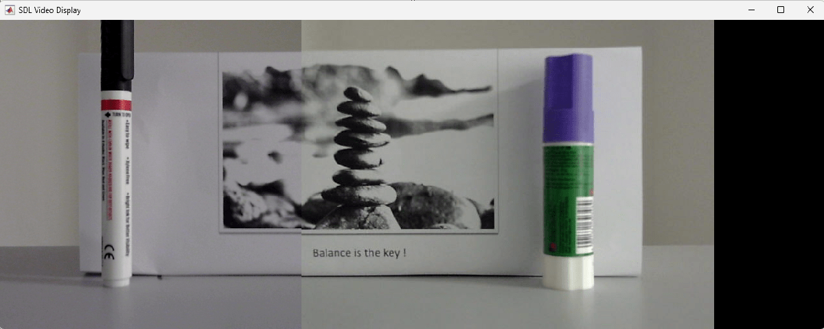
Some of the display is unused because the stitched images are not as wide as the allocated area. This portion appears as a black rectangular area.
Deploy the Model on the NVIDIA Jetson Target
Specify the directory for performing remote build process on the target board. If the directory does not exist, then software creates an new one with the given name.

Ensure that an X display client is running on the host system and find the correct display number for the connection. Set the Jetson hardware connection object to the same number by using the same number for the model via the setDisplayEnvironment method:
hwobj.setDisplayEnvironment('1.0');In Simulink, in the Hardware tab, click Build, Deploy and Start. A window with the live-stitched output opens.
Clean Up
Stop the application on the board by using the killApplication method of the Jetson hardware connection object:
hwobj.killApplication('imageStitchingComplete');