Acquire Data with Analog Input Recorder
This topic shows how to use the Analog Input Recorder app to view and record data from an NI USB-6211 device.
To open the Analog Input Recorder app, on the MATLAB® Toolstrip, on the Apps tab, in the Test and Measurement section, click Analog Input Recorder.
![]()
Once you open the app, Analog Input Recorder attempts to find all your attached analog and audio input devices.
Note
Opening Analog Input Recorder deletes all your existing
DataAcquisition interfaces in MATLAB.
You cannot access the DataAcquisition interface created by
Analog Input Recorder from the MATLAB command line.
If you plug in a device when the app is open, you must refresh the devices list to access that device. On the Devices tab, click Refresh. Use the same procedure to remove a device from the list after unplugging it.
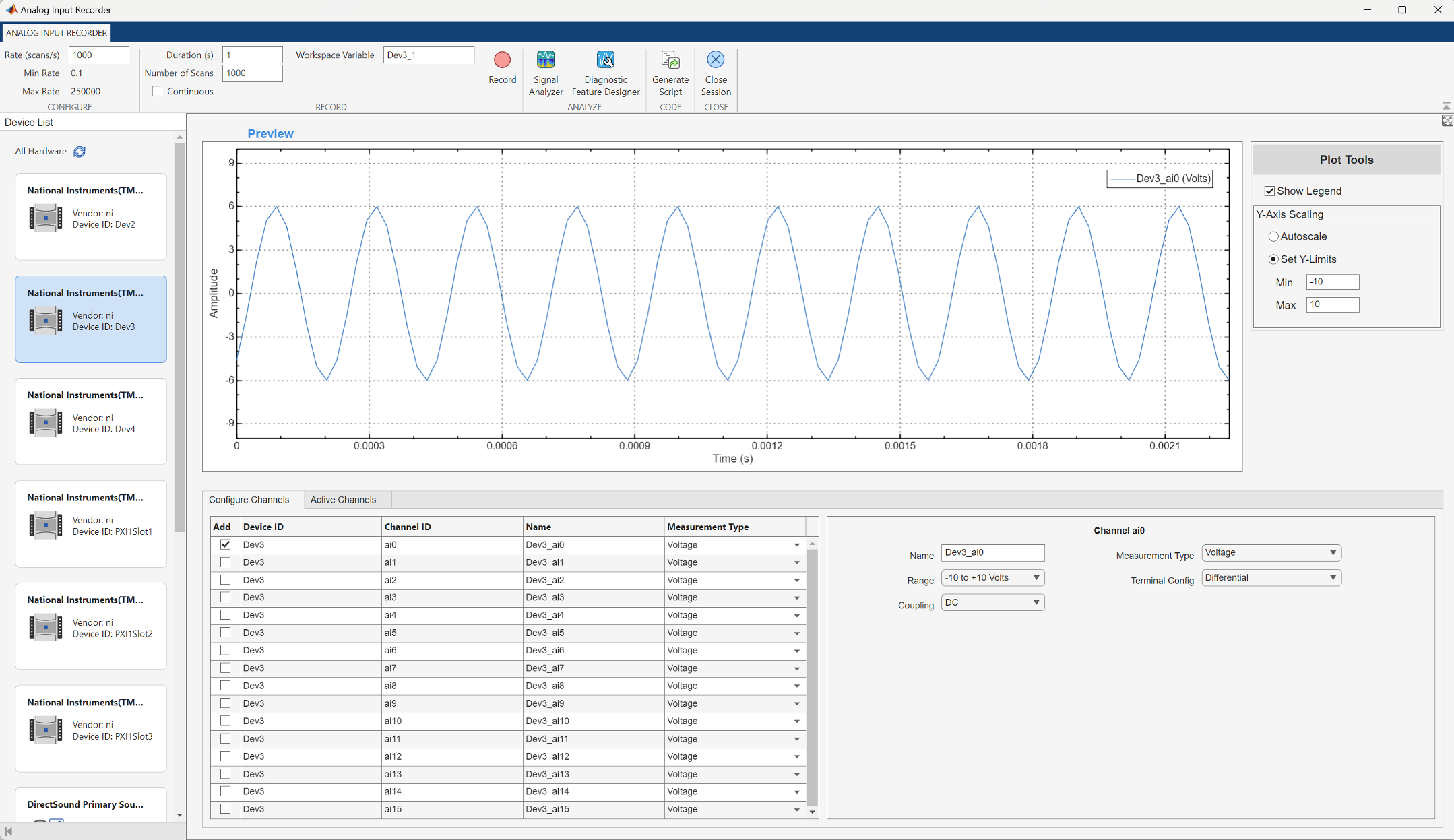
Select a device from the Device List. The app immediately provides a preview of the analog input signal using default settings.
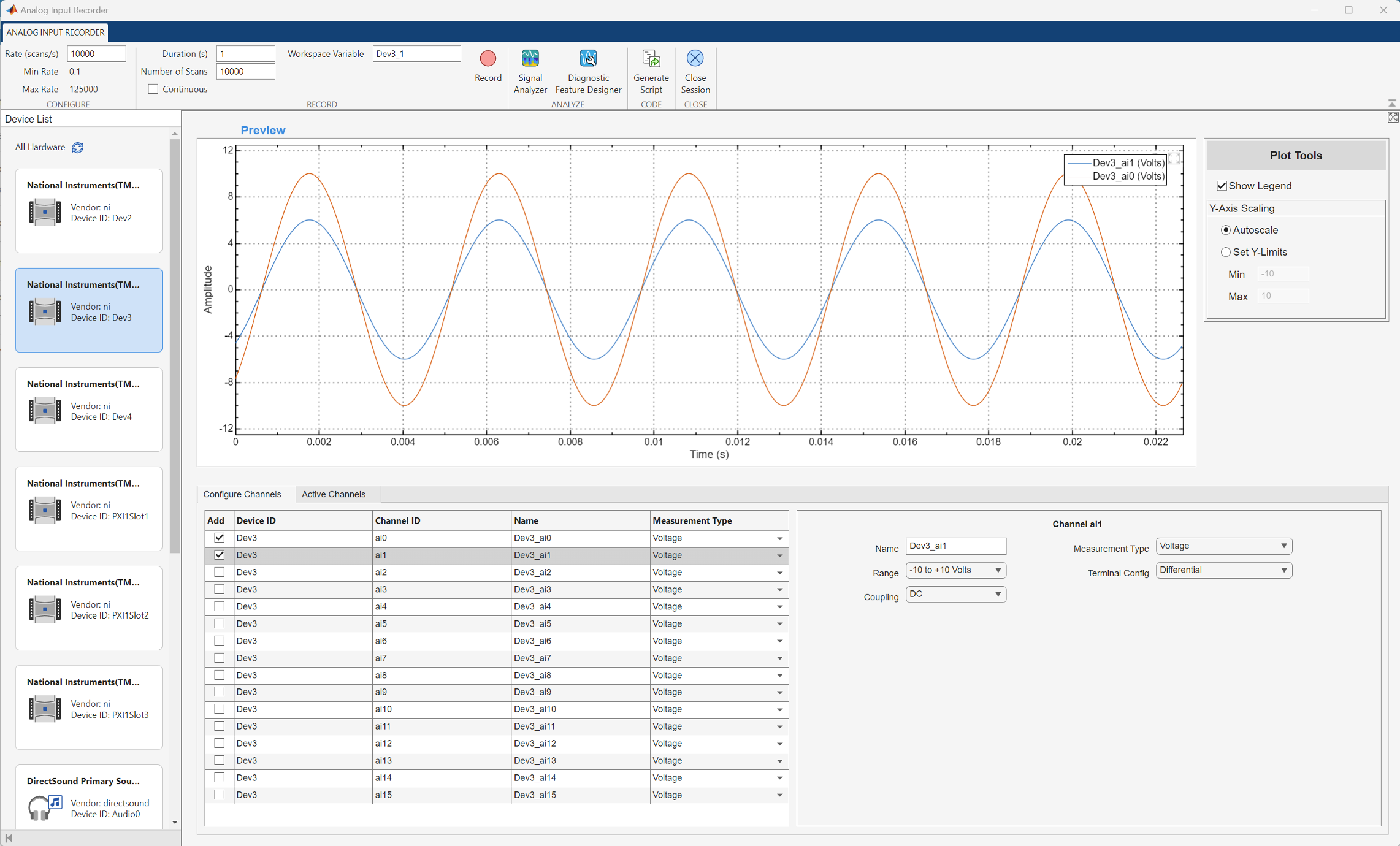
Configure Channel
You can modify the scan rate of the device or configure a selected channel. This image shows the app displaying signals from two channels of the selected device. Notice that the value of the Max Rate parameter decreases when you increase the number of selected channels. The rate of decrease depends on the selected device.
Record Session
Set the Number of Scans, Duration, and Rate parameters.
Select the Continuous parameter to override the duration or number of scans. In this mode, the app continues to record until you explicitly stop it.
Select the Workspace Variable parameter to log the recorded data
to the specified workspace variable. By default, the variable name starts with
Device ID_1, and the app increments the variable name with each
recording. You can also specify any valid MATLAB variable name that is not already in use. The app assigns the variable an
M-by-N timetable, where
M is the number of scans and N is the
number of channels.
Select the Log File
parameter to log data from an NI device to the specified TDMS file. To save the TDMS
file at a custom location, click the browse file icon ![]() . By default, the TDMS filename is the
. By default, the TDMS filename is the Device
ID and the file location is the current working directory. The app appends
data as a table in the specified TDMS file with each recording. (since R2026a)
To start recording data, click Record.
When the app finishes recording the specified number of scans or when you click Stop, the app assigns the recorded data to the specified workspace variable and appends the data to the specified TDMS file. If you have not created the file or if the specified file does not exist in the current working directory, the app creates a new file and appends the data to that file. The workspace variable contains exactly the expected number of samples, while the TDMS file may include additional data due to a brief delay between acquisition stop and hardware response.
Use this command to view the file information of timetables for a multiple channel recording.
whos
  Name          Size            Bytes  Class        Attributes

  Dev3_1      10000x2          241736  timetable
  Dev3_2      1000x2            25736  timetable
Use this command to view the first four rows of the timetable.
Dev3_1(1:4,:)
ans =
  4×2 timetable

      Time        Dev3_ai0    Dev3_ai1
    __________    ________    ________
    0 sec          -4.3578     -7.6676
    0.0001 sec     -4.2872     -7.6052
    0.0002 sec     -4.2136     -7.5304
    0.0003 sec     -4.1874     -7.4632
The timestamp elements of the table are relative to the first scan. The absolute time
of the first scan is available in the timetable in the TriggerTime
custom property. Use this command to retrieve the absolute time of the first
scan.
Dev3_1.Properties.CustomProperties.TriggerTime
  datetime

   10-Apr-2025 08:28:49.631
Use this command to view the TDMS file information.
tdmsinfo("Dev3.tdms") ans =
TdmsInfo with properties:
Path: "C:\data\tdms\Dev3.tdms"
Name: "C:\data\tdms\Dev3.tdms"
Description: ""
Title: ""
Author: ""
Version: "2.0"
ChannelList: [4×8 table]
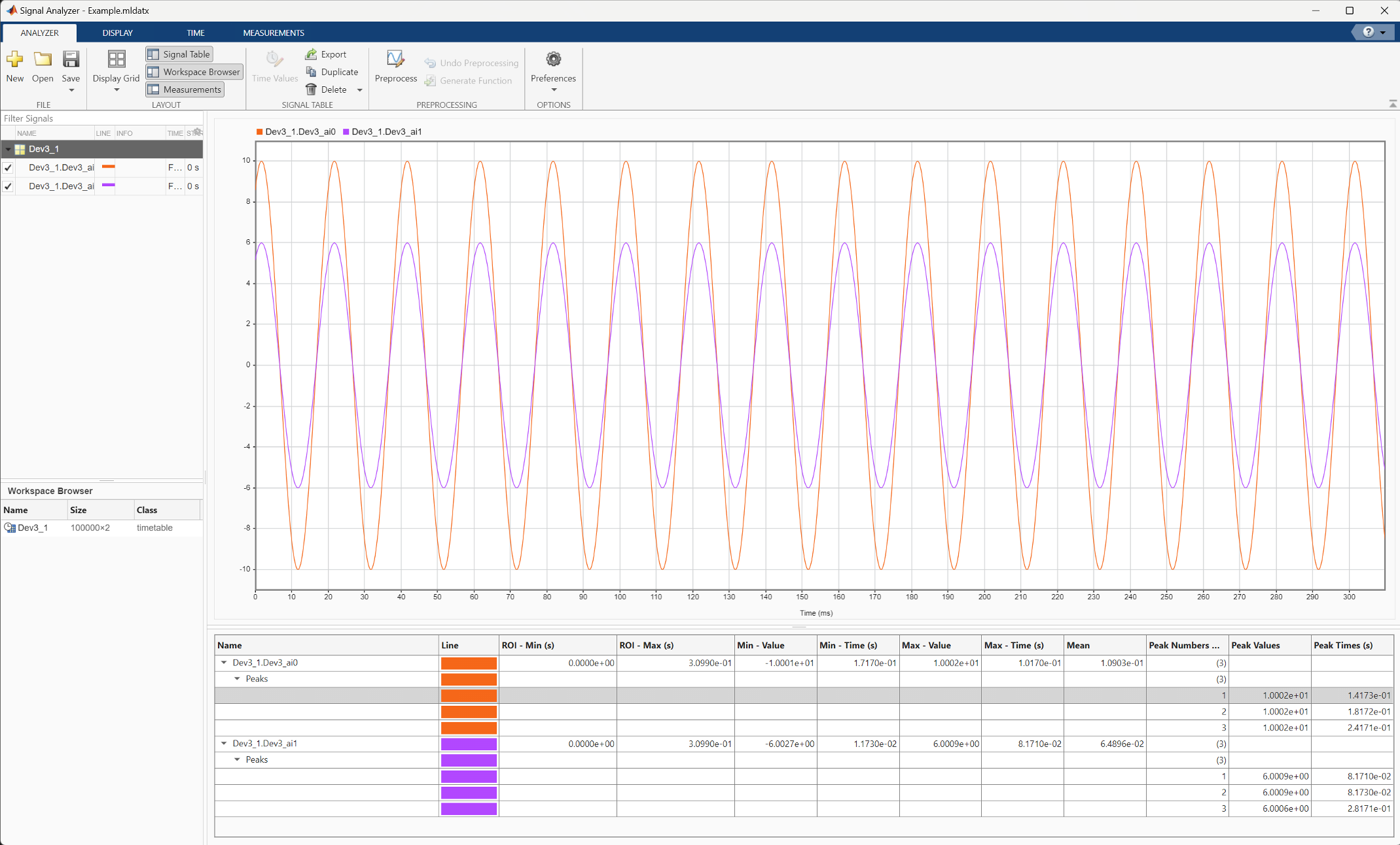
Analyze Data
In the Analog Input Recorder app, click Signal Analyzer to launch the Signal Analyzer app and display the recorded data. This image shows an analysis of signal statistics and peaks for the recorded data. For more information, see Use Signal Analyzer App (Signal Processing Toolbox).
Note
You need a license for Signal Processing Toolbox™ to use this feature.
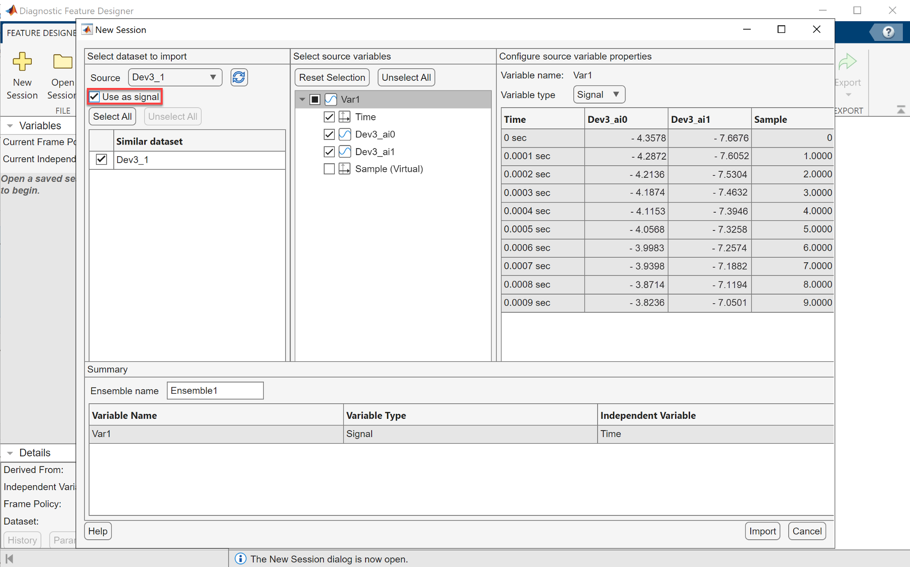
You can record data for predictive maintenance analysis using the Analog Input Recorder app. To analyze the features and identify condition indicators for machine diagnostics, click Diagnostic Feature Designer. This action launches a new session of the Diagnostic Feature Designer app with access to the recorded data. To import the recorded data as signals, select the Use as Signal parameter in the New Session dialog box. For more information, see Diagnostic Feature Designer (Predictive Maintenance Toolbox).
Note
You need a license for Predictive Maintenance Toolbox™ to use this feature.
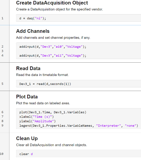
Generate Code
In the Analog Input Recorder app, click Generate Script on the app toolstrip to open MATLAB Editor and display the equivalent code for recording data. The following code is generated for a finite (non-continuous) two-channel recording from the device used in this example.