DDS Positioning System Application
This example shows how to import, model, and deploy a DDS application. The example application is a multi-sensor positioning system designed to estimate the position of a vehicle. The positioning system is composed of three components: a sensor component, an estimation component, and a display component. In the positioning system, the sensors send data to the estimation component that calculates the vehicle position estimate that it sends to the display component to show as a visual representation of the estimated vehicle position.
Import DDS Definitions for Positioning System
For the positioning system, the DDS definitions (for example, Domains, Topics, Types, and QoS policies) were specified in XML. In the general DDS Blockset workflow, you use the DDS Application Quick Start to import these XML definitions. For this example, the XML has already been imported. To view the XML specifications for the positioning system, open the XML file positioning_system.xml. To view the representation of these definitions in the DDS Blockset, open the DDS Dictionary:
open positioning_system.sldd
Model and Configure Sensor Component
The first component in the positioning system is the sensors. The positioning system uses an accelerometer and GPS, each represented by a model, to estimate the vehicle position. Each sensor model is constructed as a Publisher. To view the model structure and interface, open the models:
open_system('ex_accelerometer');
open_system('ex_gps');
In each sensor model, you can view each aspect of a Publisher modeled in Simulink:
The Sensor model logic, which is composed of a Function block that simulates sensor input data.
The Write DDS Sample block that converts the sensor data from a Simulink data type to a DDS data type.
The Bus Element Out block that sends the DDS data type.
In addition to the modeling of the sensors, the DDS interface has been configured for each sensor model. You can view the DDS interface for each sensor in the Code Mappings editor:
On the toolstrip, click the Code Interface and select Individual Elements Code Mappings.
To view the imported Topic and DataWriter for each sensor, click on the Outports tab.
Model and Configure Position Estimate Component
The second component is the estimate model. The estimate model receives data from the sensors and calculates the estimated position of the vehicle. The estimation model is constructed as a Subscriber to the sensors and as a Publisher to the display component. To view the model structure and interface, open the model:
open_system('ex_positionestimator');
In the estimation model, you can view each aspect of a Subscriber and Publisher modeled in Simulink:
The estimation model has two Bus Element In blocks configured as DDS data types to receive the sensor data.
The model has a Take DDS Sample block attached to each Bus Element In block to convert the DDS data types to Simulink data types.
The estimation model computes the logic to estimate the vehicle position.
The model uses the Write DDS Sample block to convert the Simulink data types to DDS data types.
The estimate model uses an Bus Element Out block to send the estimate as a DDS data type to the display component.
In addition to the modeling of the estimation model, the DDS interface has been configured for the estimation model. You can view the DDS interface in the Code Mappings editor:
On the toolstrip, click the Code Interface and select Individual Elements Code Mappings.
To view the imported Topics and DataReaders, click on the Inports tab.
To view the imported Topics and DataWriter, click on the Outports tab.
Model and Configure Display Component
The third component is the display model. The display model receives and graphically displays the estimated position of the vehicle. The display model is constructed as a Subscriber to the estimation component. To view the model structure and interface, open the model:
open_system('ex_resultdisplay');
In the display model, you can view each aspect of an application that acts as a Subscriber modeled in Simulink:
The estimation model has an Bus Element In block configured as a DDS data type to receive the vehicle position estimate.
The model has a Take DDS Sample block to convert the DDS data type to the Simulink data type so that it can display the vehicle estimate.
The model logic of the display component graphically shows the estimate of the vehicle position.
In addition to the modeling the display model, the DDS interface has been configured. You can view the DDS interface in the Code Mappings editor:
On the toolstrip, click the Code Interface and select Individual Elements Code Mappings.
To view the imported Topic and DataReader to receive the estimate, click on the Imports tab.
Build and Deploy Positioning System
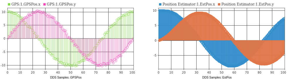
To visually show the DDS positioning system application, this example simulates the DDS network to show the results of the positioning system. A Queue block is placed between Accelerometer and Position Estimator model blocks to simulate HISTORY QoS. When you simulate the application, you can see on the dashboard that the position estimation system produces a more accurate position of the vehicle than the sensor input.
open_system('ex_positioningsystem');
set_param('ex_positioningsystem/DDS Samples: GPSPos','TimeSpan','10');
set_param('ex_positioningsystem/DDS Samples: EstPos','TimeSpan','10');
sim('ex_positioningsystem');

set_param('ex_positioningsystem/DDS Samples: GPSPos','TimeSpan','100');
set_param('ex_positioningsystem/DDS Samples: EstPos','TimeSpan','100');

To see the effect of Quality of Service (QoS) on the estimate, if the QoS is not honored the results are inaccurate.
set_param(['ex_positioningsystem/Queue for HISTORY' newline 'QoS Simulation'], ...
    'Commented','through')
set_param('ex_positioningsystem/DDS Samples: GPSPos','TimeSpan','10');
set_param('ex_positioningsystem/DDS Samples: EstPos','TimeSpan','10');
sim('ex_positioningsystem');

set_param('ex_positioningsystem/DDS Samples: GPSPos','TimeSpan','100');
set_param('ex_positioningsystem/DDS Samples: EstPos','TimeSpan','100');
After reviewing the simulation of the positioning system, if you would like to deploy this example, you can build the ex_positionestimator model and use the executable to deploy this application on the DDS network.