Coordinate Systems for Unreal Engine Simulation in Automated Driving Toolbox
Automated Driving Toolbox™ enables you to simulate your driving algorithms in a virtual environment that uses the Unreal Engine® from Epic Games®. In general, the coordinate systems used in this environment follow the conventions described in Coordinate Systems in Automated Driving Toolbox. However, when simulating in this environment, it is important to be aware of the specific differences and implementation details of the coordinate systems.
World Coordinate System
As with other Automated Driving Toolbox functionality, the simulation environment uses the right-handed Cartesian world coordinate system defined in ISO 8855. The following 2D top-view image of the Virtual Mcity scene shows the X- and Y-coordinates of the scene.

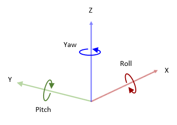
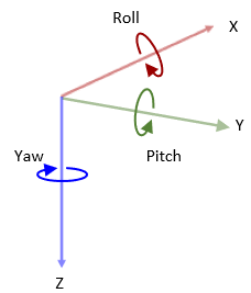
In this coordinate system, when looking in the positive direction of the X-axis, the positive Y-axis points left. The positive Z-axis points from the ground up. The yaw, pitch, and roll angles are clockwise-positive, when looking in the positive directions of the Z-, Y-, and X-axes, respectively. If you view a scene from a 2D top-down perspective, then the yaw angle is counterclockwise-positive, because you are viewing the scene in the negative direction of the Z-axis.
Placing Vehicles in a Scene
Vehicles are placed in the world coordinate system of the scenes. The figure shows how specifying the X, Y, and Yaw ports in the Simulation 3D Vehicle with Ground Following blocks determines their placement in a scene.

The elevation and banking angle of the ground determine the Z-axis, roll angle, and pitch angle of the vehicles.
Difference from Unreal Editor World Coordinates
The Unreal® Editor uses a left-handed world Cartesian coordinate system in which the positive Y-axis points right. If you are converting from the Unreal Editor coordinate system to the coordinate system of the 3D environment, you must flip the sign of the Y-axis and pitch angle. The X-axis, Z-axis, roll angle, and yaw angle are the same in both coordinate systems.
Vehicle Coordinate System
The default vehicle coordinate system is based on the world coordinate system and follows the ISO 8855 [1] standard. In this coordinate system:
The X-axis points forward from the vehicle.
The Y-axis points to the left of the vehicle.
The Z-axis points up from the ground.
Roll, pitch, and yaw are clockwise-positive when looking in the forward direction of the X-, Y-, and Z-axes, respectively. As with the world coordinate system, when looking at a vehicle from the top down, then the yaw angle is counterclockwise-positive.
The vehicle origin is on the ground, at the geometric center of the vehicle. In this figure, the blue dot represents the vehicle origin.

Mounting Sensors on a Vehicle
When you add a sensor block, such as a Simulation 3D Camera block, to your model, you can mount the sensor to a predefined vehicle location, such as the front bumper of the root center. These mounting locations are in the vehicle coordinate system. When you specify an offset from these locations, you offset from the origin of the mounting location, not from the vehicle origin. The default coordinate system for sensor blocks follow the ISO 8855 [1] standard
These equations define the vehicle coordinates for a sensor with location (X, Y, Z) and orientation (Roll, Pitch, Yaw):
(X, Y, Z) = (Xmount + Xoffset, Ymount + Yoffset, Zmount + Zoffset)
(Roll, Pitch, Yaw) = (Rollmount + Rolloffset, Pitchmount + Pitchoffset, Yawmount + Yawoffset)
The "mount" variables refer to the predefined mounting locations relative to the vehicle origin. You define these mounting locations in the Mounting location parameter of the sensor block.
The "offset" variables refer to the amount of offset from these mounting locations. You define these offsets in the Relative translation [X, Y, Z] and Relative rotation [Roll, Pitch, Yaw] parameters of the sensor block.
For example, consider a sensor mounted to the Rear bumper
location. Relative to the vehicle origin, the sensor has an orientation of (0, 0, 180).
In other words, when looking at the vehicle from the top down, the yaw angle of the
sensor is rotated counterclockwise 180 degrees.

To point the sensor 90 degrees further to the right, you need to set the
Relative rotation [Roll, Pitch, Yaw] parameter to
[0,0,90]. In other words, the sensor is rotated 270 degrees
counterclockwise relative to the vehicle origin, but it is rotated only 90 degrees
counterclockwise relative to the origin of the predefined rear bumper location.

Change Coordinate System for Vehicle and Sensors
When you add a vehicle to the scene and place a sensor on that vehicle, each get their own coordinate system which follows the ISO 8855 [1] standard. You can change the coordinate system used by the vehicle and sensors using the Coordinate system parameter in the respective blocks. Note that each coordinate system has specific units for the Relative translation [X, Y, Z] and Relative rotation [Roll, Pitch, Yaw] parameters.
This table illustrates the different coordinate systems you can choose to specify for vehicles and sensors:
| Coordinate System | Block Parameter Option | Description | |
|---|---|---|---|
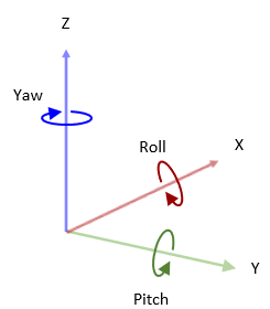
| ISO 8855 standard coordinate system | ISO8855 | The ISO 8855 standard coordinate system is a right-handed Cartesian coordinate system with Z-up orientation, in m and deg. This coordinate system is defined in the ISO 8855[1] standard. Axes
Rotation
|
|
| Unreal Engine coordinate system | Default | The Unreal Engine coordinate system is a left-handed Cartesian coordinate system, in m and rad. Axes
Rotation
|
|
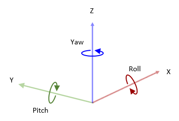
| MATLAB® coordinate system | MATLAB | The MATLAB coordinate system is a right-handed Cartesian coordinate system with Z-up orientation, in m and rad. Axes
Rotation
|
|
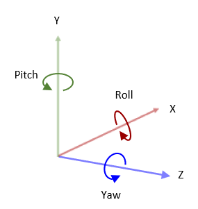
| X3D ISO standard coordinate system | VRML | The X3D ISO standard coordinate system is a right-handed Cartesian coordinate system with Y-up orientation, in m and rad. Axes
Rotation
|
|
| SAE coordinate system | SAE or AERO | The SAE J670 standard coordinate system is a right-handed Cartesian coordinate system with Z-down orientation, in m and rad. This is defined in the SAE J670[2] standard. This coordinate system is used for aerospace applications. Axes
Rotation
|
|
Difference from Cuboid Vehicle Origin
In the cuboid simulation environment, as described in Cuboid Scenario Simulation, the origin is on the ground, below the center of the rear axle of the vehicle.
| Cuboid Vehicle Origin | 3D Simulation Vehicle Origin |
|---|---|
|
|


If you are converting sensor positions between coordinate systems, then you need to account for this difference in origin by using a Cuboid To 3D Simulation block. For an example model that uses this block, see Highway Lane Following.
Difference from Unreal Editor Vehicle Coordinates
The Unreal Editor uses a left-handed Cartesian vehicle coordinate system in which the positive Y-axis points right. If you are converting from the Unreal Editor coordinate system to the coordinate system of the Unreal Engine environment, you must flip the sign of the Y-axis and pitch angle. The X-axis, Z-axis, roll angle, and yaw angle are the same in both coordinate systems.
References
[1] Technical Committee. Road vehicles — Vehicle dynamics and road-holding ability — Vocabulary. ISO 8855:2011. Geneva, Switzerland: International Organization for Standardization, 2011.
[2] Vehicle Dynamics Standards Committee. Vehicle Dynamics Terminology. SAE J670. Warrendale, PA: Society of Automotive Engineers, 2008.
See Also
Simulation 3D Vehicle with Ground Following | Cuboid To 3D Simulation