Align Parallel Data Streams
This example shows how to align two commonly sourced data streams with different upstream operation latencies using FIFO-based buffering.
In this example we use the SampleAligner to align two data streams relative to their valid signals. The SampleAligner subsystem uses FIFOs with synchronized read operations. This implementation works only if the input streams have the same number of valid samples in a time period.
The model generates a random Barker-encoded BPSK input data stream that simulates data from a transmitter. The implemented Barker decoder requires computing the cross-correlation and signal power, and then using those two signals to decode the transmitted samples. Two parallel subsystems perform cross-correlation and measure the signal power. These operations have different latencies, so to recombine the two data streams, they must be re-aligned. The cross-correlation and power measurement operations also do not change the rate or duty cycle of the shared input stream, so they are suitable for a FIFO implementation.


Stream Analyzer
To align the data streams the required buffer depth must be determined and the duty cycle of the data streams be verified as being equal. This is achieved using the StreamAnalyzer which accepts the valid signals of two data streams and determines these required parameters.
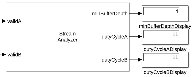
The minBufferDepth output determines the minimum number of samples that must be buffered to synchronize the data streams. This value is determined by taking the maximum modulus value of a counter which is incremented on a valid from stream A and decremented on a valid from stream B.
The dutyCycleA and dutyCycleB outputs provide the number of valid samples per second. This calculation starts counting valid samples when it receives the first valid sample on each input stream. The StreamAnalyzer's block sample time is used as the signal period when determining the dutyCycle. The duty cycle of both data streams must match to ensure that the internal buffer of the SampleAligner do not overflow. The length of the simulation affects the results of each channel's duty cycle. Longer simulations give more accurate representations of the duty cycles.
The StreamAnalyzer is for use in simulation only and does not support HDL code generation.
Sample Aligner
The SampleAligner masked subsystem aligns the samples of two data streams based on their respective valid signals. The subsystem buffers incoming data from either stream until there is at least one valid sample stored from both streams, and then reads both buffers to return a sample for each data stream. The SampleAligner requires that the valid duty cycle of the input data streams match to prevent internal buffer overflows.
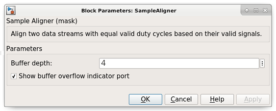
The buffer depth parameter sets the internal sample buffer depths. This parameter can be determined from analysis of the latencies for each data stream or from the use of the StreamAnalyzer. The implemented buffer depth is equal to 2^nextpow2(bufferDepth + 5). The extra 5 samples accounts for internal control logic latency when operating with continuous valid data streams.
The SampleAligner can be configured to provide an overflow indicator output port which will return a true Boolean value if either of the buffers experience an overflow. In the event of an overflow, no new data is written to the full buffer. This condition leads to loss of data integrity after the buffered samples have been output.
The SampleAligner architecture supports high clock rate applications with its frequency limit imposed by the inferred RAM type. This pipelining means the SampleAligner has a write-to-read latency of 7 clock cycles and a 4 clock cycle latency for the output of an overflow indicator. The input data types for each separate stream does not have to match. Both input streams must be scalar values.
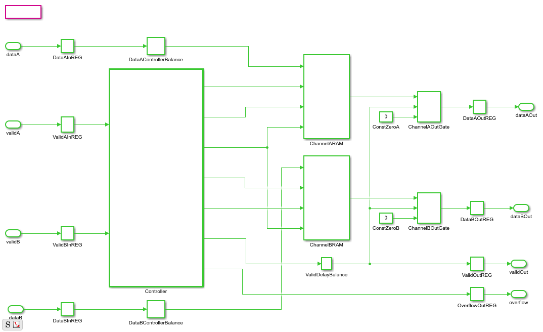
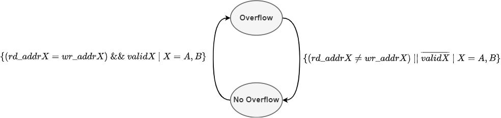
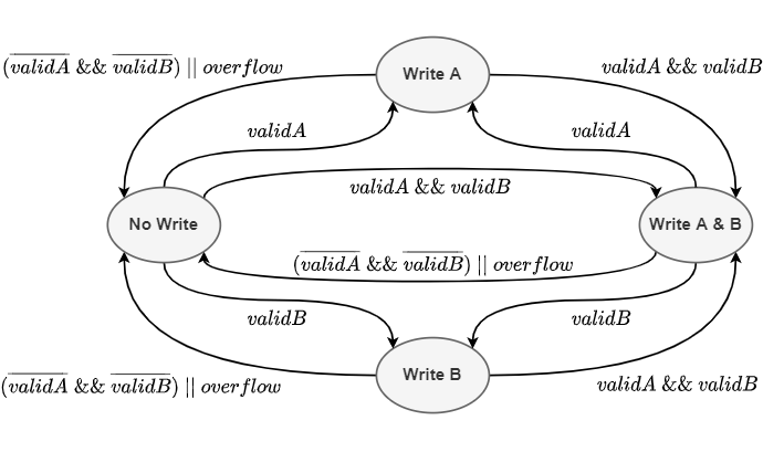
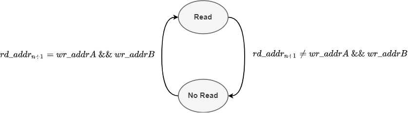
The SampleAligner Controller consists of three parallel operations which handle write and read operations. Pseudo code for these operations are shown below, with more in-depth state diagrams found at the end of example.
if (valid_A)
    if (BufferNotFull_A)
        write_A();
    else
        overflow();
    end
end
if (valid_B)
    if (BufferNotFull_B)
        write_B();
    else
        overflow();
    end
end
if (BufferNotEmpty_A) && (BufferNotEmpty_B)
    read();
end
Considerations for Stream Aligning
Performing alignment of parallel data streams is highly specific to the intended use case. The processing applied to both streams prior to the desired alignment stage as well as the downstream processing must be considered to define the alignment constraints. An equal valid duty cycle across both data streams allows for simple FIFO-based buffering. A difference in the valid duty cycles needs to be carefully handled based on the specific use case and may not be possible. Any rate changes across the data streams and the impact of filter architectures on the valid signal must be accounted for. Two data streams can have an equal duty cycle yet different pacing. One could be regular and the other could be a dense bursty stream of data. Bursty data would require a deeper buffer to ensure proper alignment. The present control signals must also be considered, with the introduction of start and end signals imposing additional alignment requirements, deeper buffers, and extended control logic.
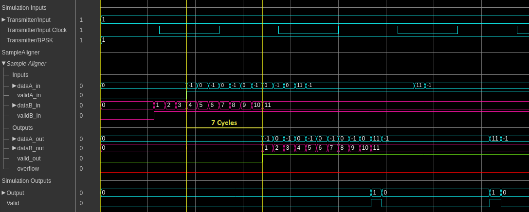
Simulation Results
The resulting simulation waveforms can be observed using the Logic Analyzer and show the SampleAligner ensure that both data streams are synchronously output.
HDL Implementation Results
The generated HDL code for the SampleAligner subsystem was synthesized for a Xilinx™ Zynq-7000 ZC706 board and met timing constraints of 649 MHz. The required resources are shown in the table.
T =

  3×2 table

    Resource     Usage
    _________    _____

    LUT           40
    LUTRAM        8
    Flip Flop     100
To check and generate the HDL code referenced in this example, you must have the HDL Coder™ product. To generate the HDL code, use this command.
makehdl('SampleAlignment/SampleAligner')
In addition to the HDL generated for this example, the SampleAligner met timing constraints on a Xilinx™ Zynq-7000 ZC706 of 649 MHz and 457 MHz for buffer depths which inferred DRAM and BRAM respectively when operating with two 16-bit data streams. The inferred RAM type is dependent on the implemented buffer size. The SampleAligner controller can see its pipelining reduced or removed to reduce the write-to-read latency if operating at lower frequencies.
Sample Aligner Controller Architecture
The following state diagrams provide a more in-depth description of the SampleAligner's controller operation.