Deploy Parametric Audio Equalizer on ARM Cortex-M Processors
This example shows how to deploy three-band parametric audio equalizer on the ARM™ Cortex™-M STM32F746G-Discovery board. You can deploy this parametric equalizer on any supported ARM Cortex-M hardware.
A parametric equalizer adjusts the frequency response of an audio system. For example, a parametric equalizer compensates for physical speakers that have peaks and dips at different frequencies.
The parametric equalizer algorithm in this example uses a second-order section (SOS) filter, whose coefficients can be adjusted to achieve a desired frequency response. The three Parametric Equalizer Design (Audio Toolbox) blocks provide the coefficients for the input parameters: gain, center frequency and bandwidth for each band. The simulation includes a user interface that enables you to dynamically adjust the equalizer parameters.
Required Hardware
ARM Cortex-M STM32F746G-Discovery board
Simulate Parametric Equalizer
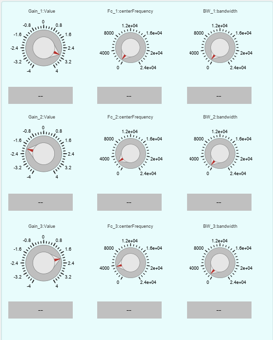
In this example, the top model stm32f746g_parametric_audio_equalizer.slx utilizes From Multimedia File block to provide audio input and employs constant blocks to supply equalizer parameters as inputs to the Parametric Equalizer. These equalizer parameters are adjusted through a user interface that includes panels with knobs for each parameter.
The model reference stm32f746g_parametric_audio_equalizer_mdlref.slx contains the actual implementation of the three-band parametric equalizer that generates the coefficients. The system then cascades these coefficients to input into the SOS filter, ensuring precise signal processing according to the specified equalizer parameters.
Open the top model and the model reference.
open_system('stm32f746g_parametric_audio_equalizer')
open_system('stm32f746g_parametric_audio_equalizer_mdlref')

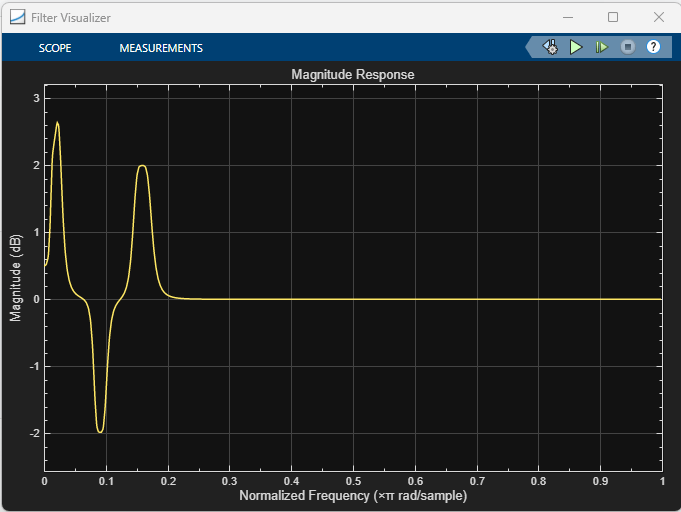
Use the Filter Visualizer block to visualize the magnitude response of the equalizer. Observe that the response changes by adjusting the specified parameters, such as gain, center frequency, and bandwidth.
The model dynamically generates the SOS filter coefficients based on these settings. You can directly perform this exploration on the STM32F746G-Discovery hardware. However, to facilitate tuning in the host simulation environment, set the Simulation mode to Normal in the block parameters of the model reference (equalizer). Additionally, consider increasing the Stop Time parameter to allow for sufficient time to tune the parameters as needed.

For more information on the equalizer parameters, see Parametric Equalizer Design (Audio Toolbox).
Configure and Deploy on ARM Cortex-M Board
You can configure the model either interactively, using Configuration Parameters in Simulink™, or programmatically, using the MATLAB™ programming interface.
Interactive Approach
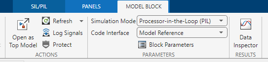
For deploying the equalizer to the target, set simulation mode of the model reference block Equalizer to Processor-in-the-Loop (PIL).
Open the top model
stm32f746g_parametric_audio_equalizer.slxand select theEqualizerblock to enable Model Block tab on the Simulink Toolstrip. Then, set Simulation Mode toProcessor-in-the-Loop (PIL).
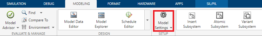
Press Ctrl+E in the model reference or open the Modeling tab and select Model Settings from the toolstrip to open the Configuration Parameters dialog box.
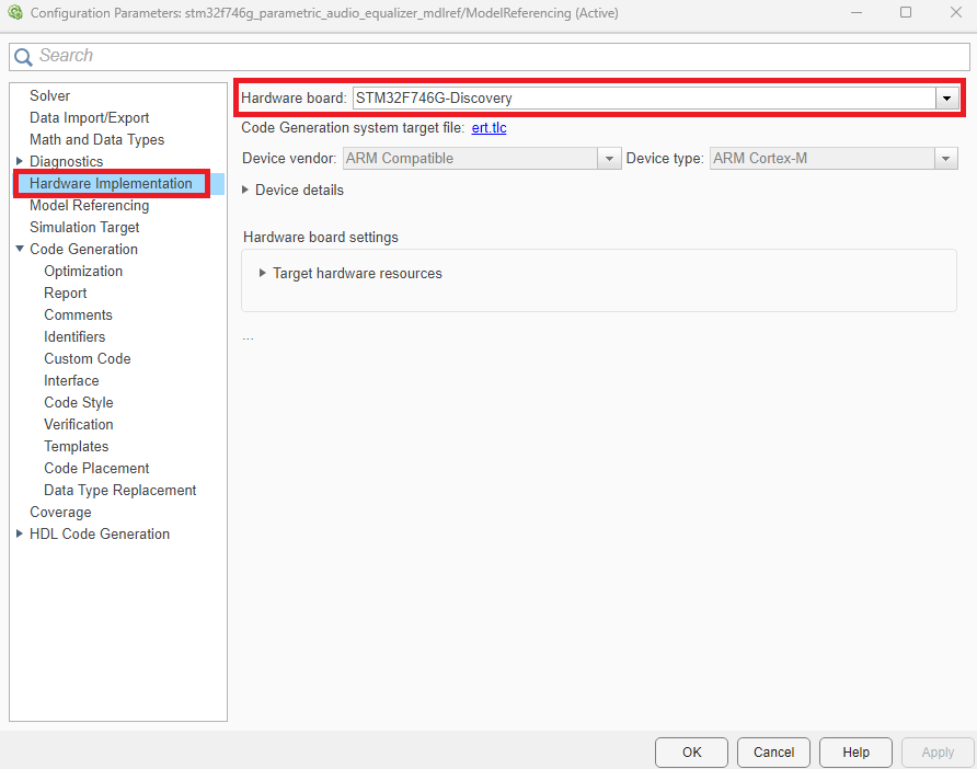
Go to Hardware Implementation and set Hardware board to
STM32F746G-Discovery.
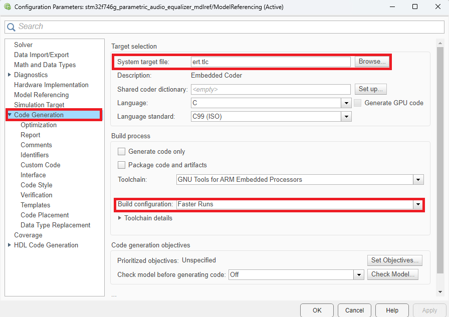
In the left pane, select Code Generation and specify these settings.
Set System target file to
ert.tlc.Set Build Configuration to
Faster Runs.
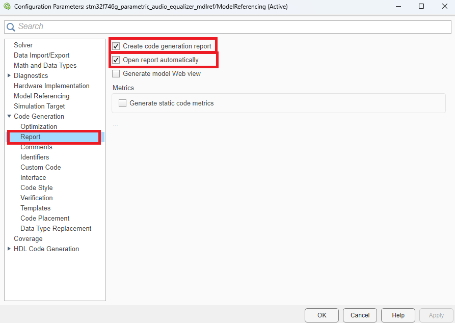
Go to Report and select Create code generation report, Open report automatically.
Programmatic Approach
Execute the following commands to configure the Simulink model stm32f746g_parametric_audio_equalizer_mdlref.slx for deployment on the STM32F746G-Discovery board. Select ert.tlc as the system target file to optimize the code for embedded real-time systems, and choose Faster Runs for the build configuration to prioritize execution speed. Ensure that the Hardware board settings like Drive and COM Ports are set appropriately.
set_param('stm32f746g_parametric_audio_equalizer_mdlref','HardwareBoard','STM32F746G-Discovery');
set_param('stm32f746g_parametric_audio_equalizer_mdlref','SystemTargetFile','ert.tlc');
set_param('stm32f746g_parametric_audio_equalizer_mdlref','BuildConfiguration','Faster Runs');
Finally, enable the generation of detailed code replacement reports. These reports provide valuable insights into the code structure, facilitating a deeper understanding of the deployment process.
set_param('stm32f746g_parametric_audio_equalizer_mdlref','GenerateReport','on');
set_param('stm32f746g_parametric_audio_equalizer_mdlref','GenerateCodeReplacementReport','on');
Run on Target
Enter this command to run the model programmatically in PIL mode. Alternatively, you can run the model in PIL mode interactively. On the Simulation tab of Simulink Toolstrip, select 'Run'. You can increase the 'Stop Time' parameter to allow for sufficient time to tune the parameters as needed.
sim('stm32f746g_parametric_audio_equalizer','StopTime','1')
The simulation runs on the STM32F746G-Discovery board. You can tune the parameters such as gain, center frequency, and bandwidth during the simulation, and the model dynamically generates the SOS Filter coefficients. You can view the magnitude response of the tuned equalizer using the Filter Visualizer.
For detailed information on the generated code, view the Code Generation Report.
