Contenu principal

PIM Peripheral Configuration

R2026b

Configure PIM block peripherals

Since R2026b

Description

Add-On Required: This feature requires the Embedded Coder Support Package for Infineon AURIX TC4x Microcontrollers add-on.

Configure the Pulse input measurement (PIM) block peripherals and map them to the corresponding peripheral registers on the Infineon® AURIX™ Microcontroller board.

This mapping ensures that the generated code uses the intended hardware resources and helps identify peripheral configuration conflicts before deployment.

Open the PIM Peripheral Configuration

Follow these steps to configure PIM peripherals in the Hardware Mapping tool.

  1. To access the configuration parameters, in the model, on the Modeling tab, click Model Settings. In the Hardware Implementation pane, set Hardware board to Infineon AURIX TC4x.

  2. To open the Hardware Mapping tool, in the Simulink editor, on the Hardware tab, click Hardware Mapping.

    Hardware Mapping

  3. In the Mapping Browser pane:

    • To configure the PIM clock configuration, navigate to Peripherals > PIM.

    • To configure the PIM peripheral configuration, navigate to Peripherals > PIM > PIM.
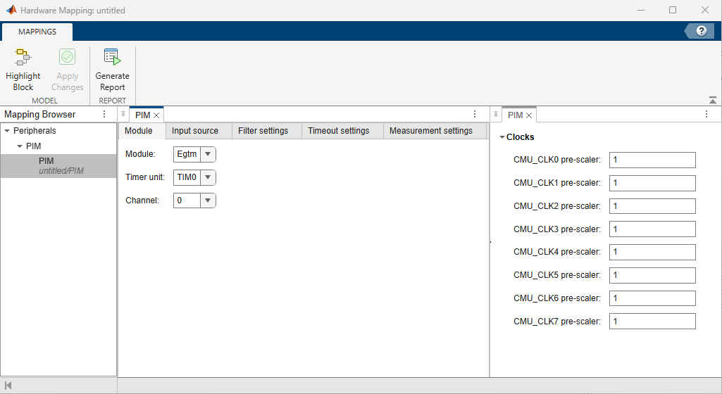
    PIM peripheral configuration in Hardware Mapping Tool

Parameters

expand all

Global parameters > Clocks

Specify the prescaler value for the CMU configurable clock. The module frequency is divided by this value to determine the clock frequency used for filtering, timeout monitoring, and measurement. Eight configurable clocks (CMU_CLK0 through CMU_CLK7) are available.

PIM > Module

Select the generic timer module (GTM) or enhanced generic timer module (EGTM) for PWM input measurement.

Select the TIM unit for capturing the input signal. Available options depend on the selected module.

Select the TIM channel number for capturing the input signal.

PIM > Input source

Select the input signal source for PWM measurement. Select External pin to capture a signal from a hardware pin, or select Internal signal to capture a signal from the internal timer output module (TOM) or ARU-connected timer output module (ATOM) channel output.

For the Internal signal option, the Module, Channel parameter values of the PIM block must match the Module and Channel n parameter values of the PWM block.

Select the internal signal source for PWM measurement. To view the Previous channel option, set the Channel parameter to a value other than 0. This option captures the output of the adjacent TIM channel.

Dependencies

To enable this parameter, set the Input parameter to Internal signal.

Select the hardware pin to use as the input source for PWM signal capture.

Dependencies

To enable this parameter, set the Input parameter to External pin.

Select one of these configuration modes for the PIM input pin.

  • Pull-up — Enables an internal pull-up resistor to provide a default high logic level on the input pin when it is not driven.

  • Pull-down — Enables an internal pull-down resistor to provide a default low logic level on the input pin when it is not driven.

Dependencies

To enable this parameter, set the Input parameter to External pin.

Select the TOM or ATOM unit that provides the internal signal source.

Dependencies

To enable this parameter, set the Input parameter to Internal signal and Source parameter to Egtm.

Select the specific channel output signal to use as the internal input source. Options include direct channel outputs and complementary (inverted) outputs.

Dependencies

To enable this parameter, set the Input parameter to Internal signal and Source parameter to Egtm.

PIM > Filter settings > Filter Configuration

Select this parameter to bypass the input signal filter. Disable this parameter to enable input signal filtering with configurable debounce settings for rising and falling edges.

Select the CMU clock source for input signal filtering. The filter clock frequency determines the minimum detectable edge time.

Dependencies

To enable this parameter, disable the Bypass filtering parameter.

PIM > Filter settings > Rising edge debounce settings

Select one of these debounce filter modes for rising edges:

  • Immediate edge propagation — To pass edges through without debounce.

  • De-glitch up-down — To use an up-down counter for debouncing.

  • De-glitch hold — To hold the signal level for the specified filter time.

Dependencies

To enable this parameter, disable the Bypass filtering parameter.

Specify the debounce filter time for rising edges in seconds.

Dependencies

To enable this parameter, disable the Bypass filtering parameter.

PIM > Filter settings > Falling edge debounce settings

Select one of these debounce filter modes for falling edges:

  • Immediate edge propagation — To pass edges through without debounce.

  • De-glitch up-down — To use an up-down counter for debouncing.

  • De-glitch hold — To hold the signal level for the specified filter time.

Dependencies

To enable this parameter, disable the Bypass filtering parameter.

Specify the debounce filter time for falling edges in seconds.

Dependencies

To enable this parameter, disable the Bypass filtering parameter.

PIM > Timeout settings > Timeout Configuration

Select the CMU clock source for timeout monitoring. The timeout clock frequency determines the minimum configurable timeout period.

Dependencies

To enable this parameter, select the Timeout status block parameter.

Specify the timeout duration in seconds. If no signal edge is detected within this time, the block sets the timeout status output to 1.

Dependencies

To enable this parameter, select the Timeout status block parameter.

PIM > Measurement settings > Measurement Configuration

Select the edge alignment and active polarity for the PWM measurement. This parameter determines which signal edges the TIM uses to measure period and duty cycle.

Select the CMU clock source for period and duty cycle measurement. The clock frequency determines the measurement resolution and maximum measurable period.

Select this parameter to generate an interrupt when the TIM channel completes a period measurement.

Select this parameter to generate an interrupt when the measurement counter overflows. A counter overflow indicates that the input signal period exceeds the maximum measurable range of the timer.

Version History

Introduced in R2026b

See Also

|