Custom Storage Class for Infineon AURIX TC4x Microcontrollers
This example shows how to define a custom storage class for Infineon® AURIX™ TC4x Microcontrollers using Embedded Coder® Support Package for Infineon® AURIX™ TC4x Microcontrollers.
A storage class controls the code generated for model data and the memory section controls the placement of data and functions in memory. To enable applications to control the placement of model data elements (global variables) and model function elements in memory, define a custom storage class and memory section.
You can use the custom storage class approach to select placement of data and code elements for your application in any TriCore core memory of the device.
For example, to define custom storage in a linker configuration file, specify named sections in a SECTIONS directive and map each section to a range of memory addresses. This enables you to use the compiler pragma that assigns global variables and functions to these named sections and, by extension, to the memory ranges. For more information, see Control Data and Function Placement in Memory by Inserting Pragmas.
Supported Memory Sections
This table lists the different memory sections currently available for Infineon AURIX TC4x Microcontrollers in the custom storage class package named aurixmemorydemospkg.
Memory Section | Section name on TriCoreX |
|---|---|
Bss (DSRAM) | bssTriCoreX |
BssLMU (dLMU) | bssLMUTriCoreX |
Data (DSRAM) | dataTriCoreX |
DataLMU (dLMU) | dataLMUTriCoreX |
Code (RAM) | codeRAMTriCoreX |
Code (Flash) | codeFlashTriCoreX |
This table lists the different storage classes currently available for Infineon AURIX TC4x Microcontrollers in the custom storage class package named aurixmemorydemospkg.
Storage Class | Section name on TriCoreX |
|---|---|
Exported Global Bss | ExportedGlobalbssTriCoreX |
Exported Global Bss LMU | ExportedGlobalbssLMUTriCoreX |
Exported Global Data | ExportedGlobaldataTriCoreX |
Exported Global Data LMU | ExportedGlobaldataLMUTriCoreX |
X can be 0,1,2, and so on depending upon the TriCores available on the device.
This package also includes the storage classes ExportedGlobalbssLMUGlobal and ExportedGlobaldataLMUGlobal, as well as the memory sections bssLMUGlobal and dataLMUGlobal for storing global variables, code, and data.
Load aurixmemorydemospkg in Model
The AURIX Microcontrollers code interface definitions (storage class and memory section) are configured and stored in an Embedded Coder Dictionary package named aurixmemorydemospkg.
To load the aurixmemorydemospkg package in a Simulink® model:
1. Configure a valid Infineon AURIX hardware board. Open the Configuration Parameters dialog box. In the Hardware Implementation pane, set Hardware board to Infineon AURIX™ TC4x.
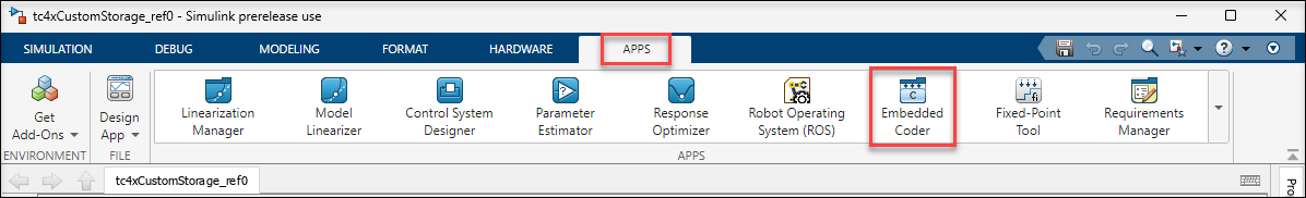
2. To enable the embedded coder features, select Embedded Coder from the Apps gallery in the Apps tab. This action adds a C Code tab to the toolstrip. In the C Code tab, select Code Interface > Embedded Coder Dictionary.
3. The Embedded Coder Dictionary window displays the code interface configuration that is stored in the dictionary. In the left pane of the dictionary window, select Memory and click Manage Packages.
4. In the Manage Packages window, click Refresh and Set Select package to aurixmemorydemospkg. To load the package in the model, click Load.
5. To view the code interface definitions that are part of aurixmemorydemospkg, click Storage Class and Memory Section from the left pane of the Embedded Coder Dictionary window.
Model Description
The top model tc4xCustomStorageTop and the reference models tc4xCustomStorage_ref0, tc4xCustomStorage_ref1, and tc4xCustomStorage_ref3 are included with this example and are set up using the custom storage class and memory sections from aurixmemorydemospkg. Each reference model is set up for an individual Tricore. In this example, the reference models ending with ref0, ref1, and ref3 are set up for Tricore0, Tricore1, and Tricore3, respectively.
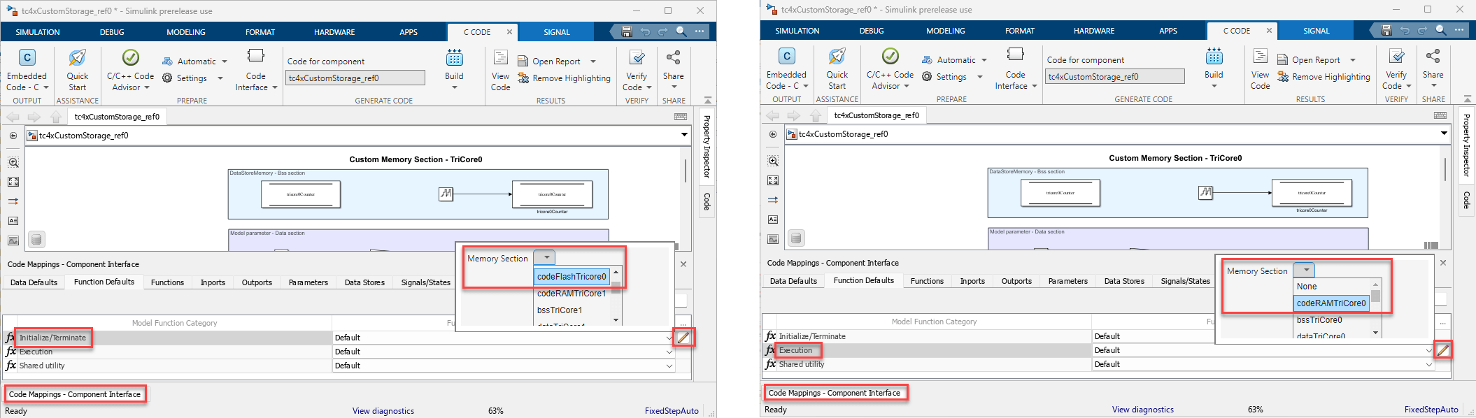
To configure model elements for code generation, use Code Mappings Editor — C as the primary location. Each element in the attached example models is configured for code generation using code mappings. This example shows how to configure the memory sections and storage classes for data and code in the reference model tc4xCustomStorage_ref0. The other reference models are configured with similar settings. Based on your application, you can modify these settings for the data and code in your models.
Configure Custom Memory Section for Data
1. Open the top model tc4xCustomStorageTop and reference model tc4xCustomStorage_ref0.
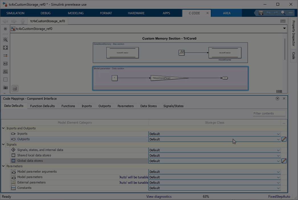
2. In the reference model, open the Embedded Coder app to enable the C Code tab and the Code Mappings - Component Interface. For more information, see C Data Code Interface Configuration for Model Interface Elements.
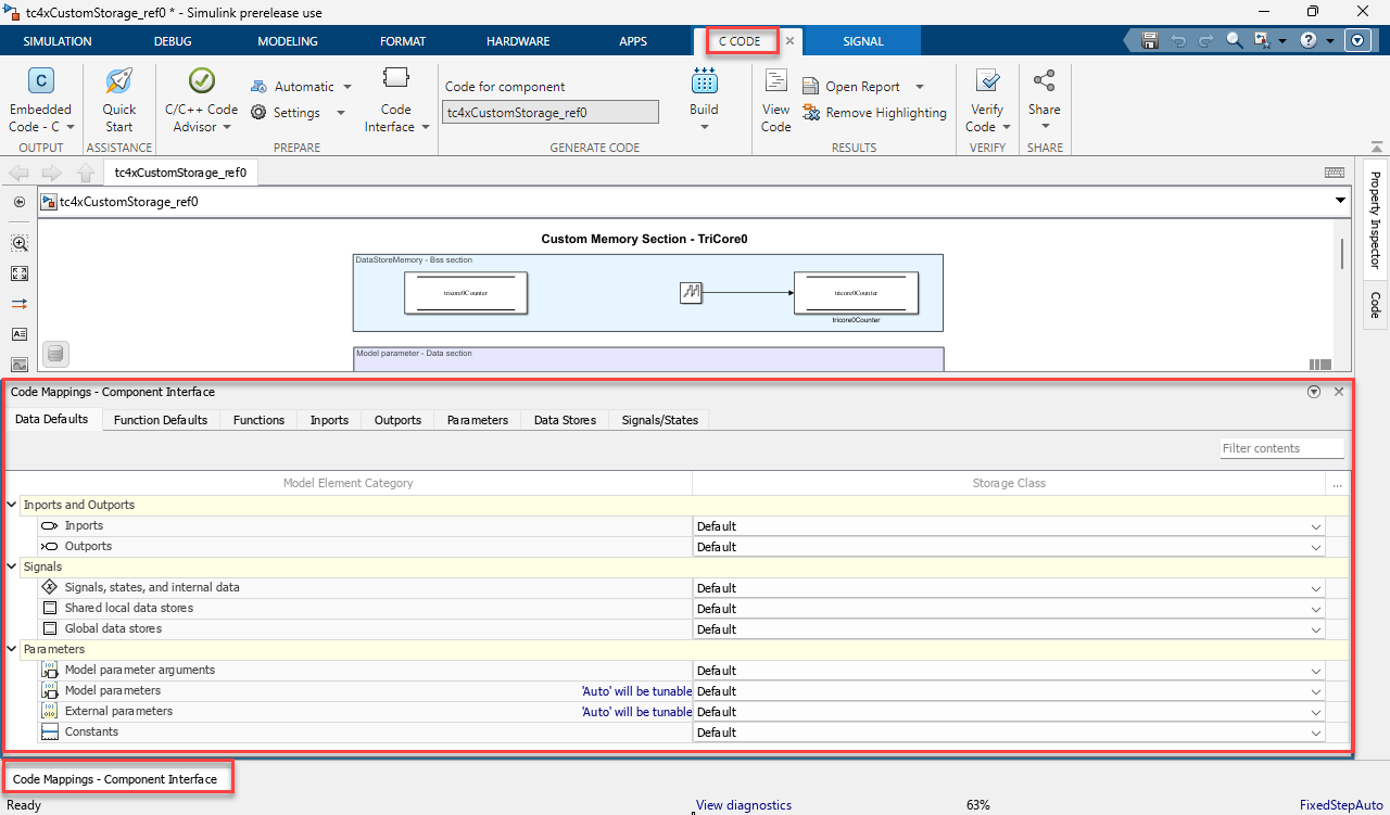
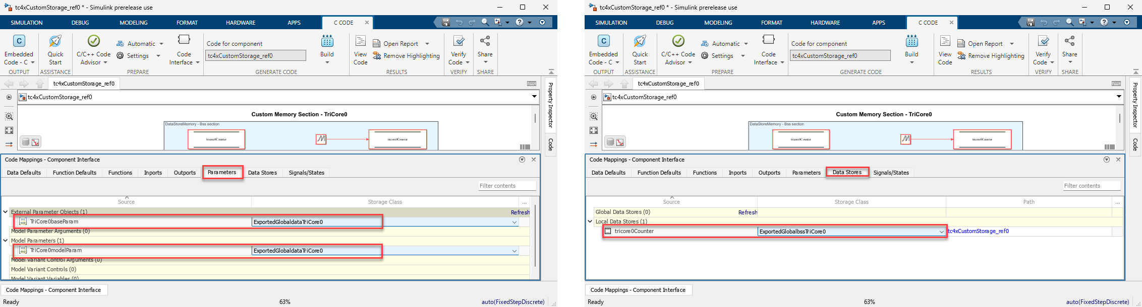
3. The model contains data elements such as workspace parameters, model parameters and data store memory. You can map each of these data elements to a specific memory section using the Code Mappings Editor.
4. In the Code Mappings - Component Interface, map the external parameter, also called as the workspace parameter TriCore0baseParam to the data section of TriCore0. Similarly, map the model parameter TriCore0modelParam and the data store element tricore0Counter to the data and bss section of Tricore0, respectively.
These are the code mappings assigned for data elements in reference model tc4xCustomStorage_ref0.
Parameter Name | Parameter Type | Memory Section |
|---|---|---|
| External parameter |
|
| Model parameter |
|
| Datastore |
|
Note: You can use code mappings to configure the memory section for other data elements in the model, such as constants, signals, internal data, and more.
Configure Custom Memory Section for Code
To specify code generation requirements for model functions, configure the custom memory section for code using the Code Mappings Editor.
1. Open the top model tc4xCustomStorageTop and reference model tc4xCustomStorage_ref0.
2. In the reference model, open the Embedded Coder app to enable the C Code tab and the Code Mappings - Component Interface. For more information, see C Data Code Interface Configuration for Model Interface Elements.
3. Depending upon the application requirements, you can place these model functions either in flash or RAM memory. This example assumes these code generation requirements:
a. Store the model initialize and terminate entry-point functions in the slow memory (flash).
b. Store the execution function in fast memory (RAM).
4. In the Code Mappings - Component Interface, map the Initialize/Terminate and Execution functions to the codeFlashTricore0 and codeRAMTricore0 memory sections, respectively.
These code mappings are assigned for model functions in reference model tc4xCustomStorage_ref0.
Function Name | Function Type | Memory Section |
|---|---|---|
| Initialize |
|
| Terminate |
|
| Execution |
|
Configure Custom Storage Class
To control the appearance of data in the generated code and to prevent optimizations from eliminating individual data elements, configure the storage class for parameters and datastores using the Code Mappings editor. This example configures the parameters and datastores individually as separate global variables by mapping them to the custom storage classes ExportedGlobaldataTriCore0 and ExportedGlobalbssTriCore0, respectively. These custom storage classes are provided with the aurixmemorydemospkg package.
Based on your application requirements you can define and use a new custom storage class. For more information, see:
Verify Memory Placement for Model Data and Code
To verify that the data and code elements are placed in the appropriate memory sections and the code is generated as per the configured storage class:
1. Build the top model tc4xCustomStorageTop.
2. In the generated code folder, locate a MAP file named tc4xCustomStorageTop.map and verify the address information for the data and code. For example, this table lists the address information for data and code in the reference model tc4xCustomStorage_ref0.
Parameter Name | Definition Section | Section Address | Parameter Address |
|---|---|---|---|
|
| 0x700001a4 | 0x700001a4 |
|
| 0x700001a4 | 0x700001a6 |
|
| 0x700001a8 | 0x700001a8 |
Function Name | Definition Section | Section Address | Function Address |
|---|---|---|---|
|
| 0x8000474c | 0x8000474c |
|
| 0x70100000 | 0x70100000 |
Update and Add Custom Linker File
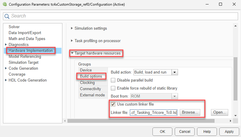
Optionally, to configure your Simulink model with a custom linker file, press Ctrl+E or select Modeling > Model Settings to open the Configuration Parameters dialog box.
In the Hardware Implementation pane, expand Target hardware resources option.
Click Startup options group and select Use custom linker file option.
Click Browse and select the custom Linker file.
When using a tasking compiler and a custom linker file, update the linker command file to allocate the function code to the CPU-specific flash section memory area. This will enable the supported memory sections from the aurixmemorydemospkg package.
This image shows a code snippet of the default linker file used in this example. The highlighted line of code allocates the function code created as .text to the pfls0 memory area.

Known Limitation
Embedded Coder® Support Package for Infineon® AURIX™ TC4x Microcontrollers does not support custom storage class and custom memory sections with the GCC for AURIX™ TriCore based on AURIX Development Studio compiler.
The
bssLMUGlobalanddataLMUglobalmemory sections of theExportedGlobalbssLMUGlobalandExportedGlobaldataLMU Globalstorage classes are supported only for the TriCore 0 processing unit. You can uses these memory sections for an SoC-based multicore model using separate ELF workflow or a TriCore 0 based monolithic models. For more information on these workflows, see SoC-Based Multicore Modeling Workflow for Infineon AURIX Microcontrollers, Monolithic Modeling for Infineon AURIX Microcontrollers, and Generate Software Executables for Multicore Models.
Other Things to try
Verify the memory placement for the other reference models that are provided with this example.
Use other compilers to verify the memory placement.