Integrate Code Generated for Infineon TC3x with ADS Workflow
This example shows how to export code generated from Simulink® using Embedded Coder® Support Package for Infineon® AURIX™ TC3x Microcontrollers and deploy the code to hardware using AURIX Development Studio (ADS).
In this example, you use a Simulink model to implement an algorithm to control LED intensity. You export the code generated for the model to an ADS project for code integration and build testing. After successfully building the code, you deploy the code on an Infineon AURIX™ Lite Kit to control the intensity of the on-board LED using the on-board potentiometer.
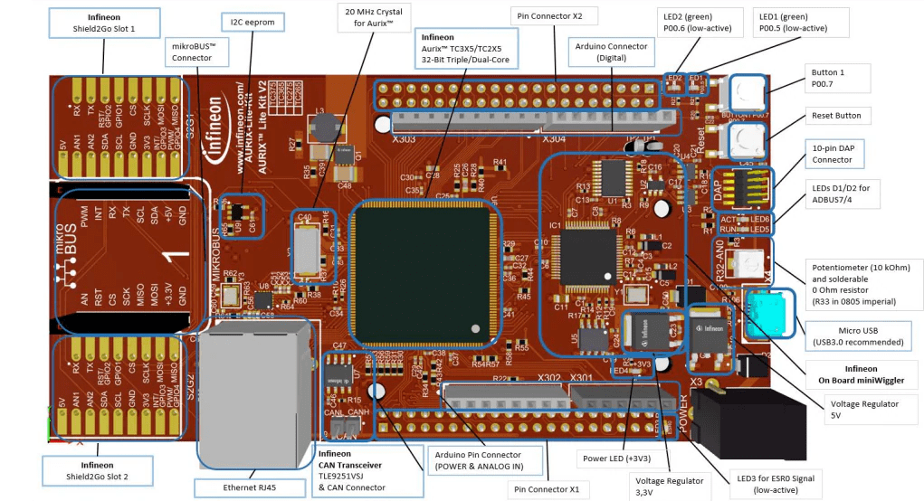
Required Hardware
Infineon AURIX™ Lite Kit
Model Description
The AdcCountsToDutyCycle model, included in this example, processes an ADC count value received from a sensor. The algorithm in the model first converts the count value into volts and then transforms it into a duty cycle percentage. The model uses two gain blocks to show these conversions separately in the generated code. It outputs the calculated duty cycle as a percentage. All blocks within the model operate with the same sampling time.

In this example, you use the value from a potentiometer connected to Pin AN0 as the sensor input and direct the duty cycle output to an LED on Port 0 Pin 5 of an Infineon AURIX™ Lite Kit.
Model Configuration
Configure the Simulink model to generate code based on the hardware application requirements. Use these settings to generate maintainable code that you can deploy to any microcontroller:
Fixed-step solver Evaluates model at a constant time step
Target file
ert.tlcGenerates optimized C code for embedded systemsGenerate code only Generates code without building an executable, allowing you to inspect and modify code before deploying to hardware
Package code and artifacts Packages code and all the related artifacts required for a development environment, such as header files and build scripts
C data types with fixed width integers Generates readable code
You can configure a model programmatically using the CLI or graphically using the GUI.
Programmatic Approach for Model Configuration
This script configures your model programmatically to use a fixed-step solver and an embedded coder target. In addition, it configures the code generation settings, such as the options to generate only code, package code and related artifacts, and use fixed width for data types.
set_param(bdroot,'SolverType','Fixed-step');
set_param(bdroot,'SystemTargetFile','ert.tlc') ;
set_param(bdroot,'GenCodeOnly','on');
set_param(bdroot,'PackageGeneratedCodeAndArtifacts','on');
set_param(bdroot,'DataTypeReplacement','CDataTypesFixedWidth');
GUI Approach for Model Configuration
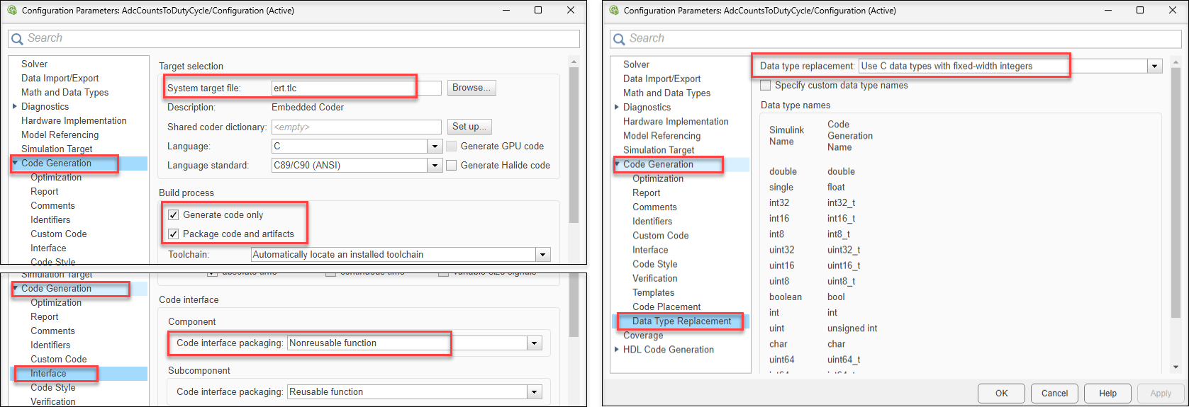
To configure the model using the GUI, press CTRL + E or click Model settings in the Modeling tab to open the Configuration Parameters dialog box.
1. In the Code Generation pane, set System target file to ert.tlc, and select the Generate code only and Package code and artifacts options.
2. Expand the Code Generation pane to view additional options.
Click Interface and then set Code interface packaging to
Nonreusable function.Click Data Type Replacement and then set Data type replacement to
Use C data types with fixed-width integers.
3. Click OK to apply the configuration settings.
Code Generation
You can configure the code generation settings for this example in two ways:
case (i) Set all model elements to the default storage class.
case (ii) Configure the inports and outports for data import and export using the
ImportedExternandExportedGlobalstorage classes, respectively.
To configure model elements for code generation, use Code Mappings Editor.
1. In the Simulink model, open the Embedded Coder app to enable the C Code tab and the Code Mappings - Component Interface.
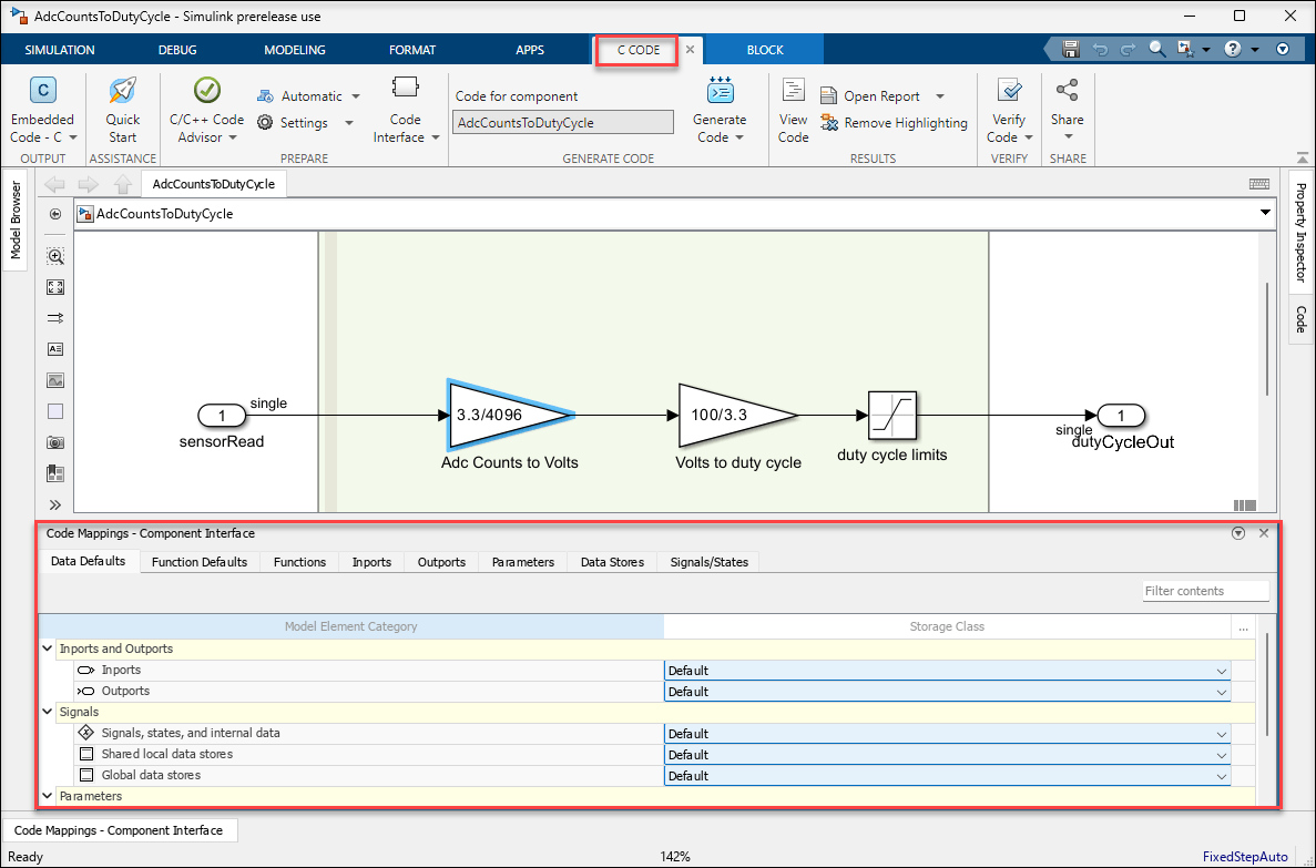
2. In case (i), all model elements use the default storage class. For applications that require data import or export from the model, set the Inports and Outports options to the ImportedExtern and ExportedGlobal storage class, respectively.

3. In the Functions tab, double-click the second entry from the function preview to configure the generated C function interface, including function name and arguments. If you do not use the default storage class you can only modify the function name.
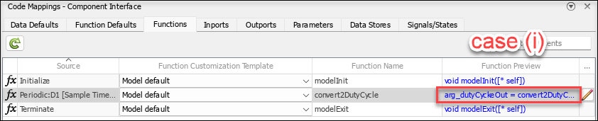
If you use the default storage class, you can update these settings in the configure window.
Specify C Step Function Name as
convert2DutyCycle.Select the Configure arguments for Step function prototype option.
To populate Port Name and Port Type information from model, click Get default.
Set C return argument to
dutyCycleOut.Specify C Identifier Name as
arg_sensorRead.To validate the settings for the function, click Validate.
Once the function settings are successfully validated, click OK.

4. To generate and package code, press CTRL + B or click Generate Code from the C Code tab.
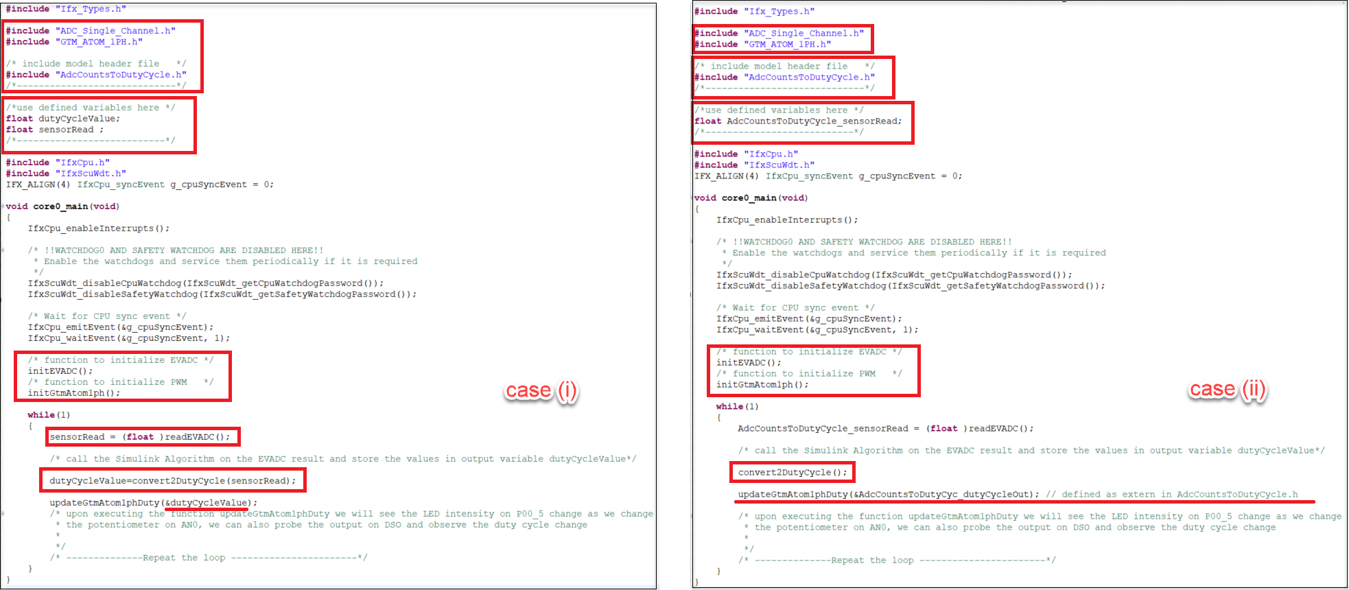
These images show snippets of the generated code for two modelling scenarios.
case (i) when the model uses a default storage class for inports and outports.
case (ii) when the model uses
ImportedExternandExportedGlobalstorage class for inports and outports, respectively. In this case the output port is defined as the global variabledutyCycleOut.

Create ADS Project and Import Generated Code
AURIX Development Studio (ADS) is an Eclipse-based Infineon IDE used for embedded development of Infineon microcontrollers. This example uses IDE version AURIX-v1.9.6-L, which you can download here.
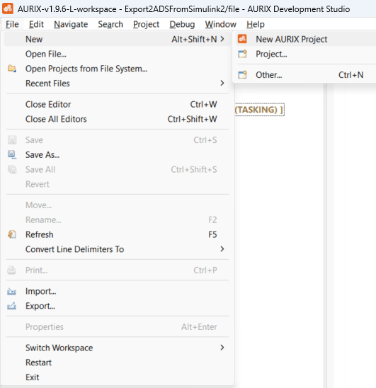
1. To create a new project, click the File menu in AURIX Development Studio and select New > New AURIX Project.
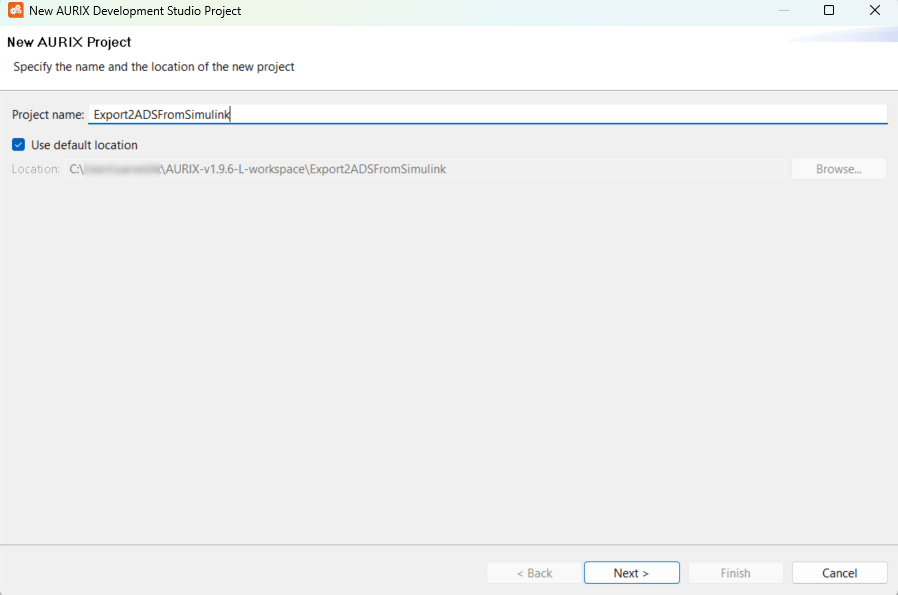
2. In the new project window, specify a project name, choose a project location and click Next. This example uses a project named Export2ADSFromSimulink.
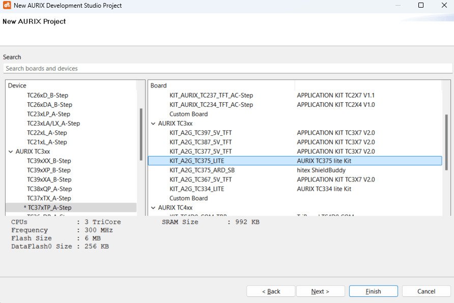
3. Select the board name and click Finish. This example uses the AURIX KIT_A2G_TC375_LITE board.
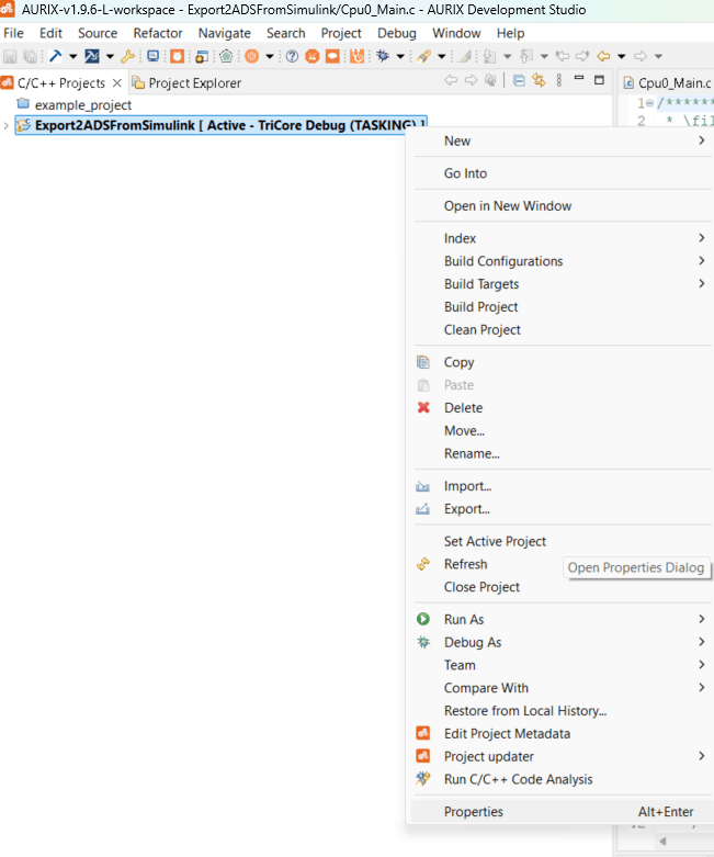
4. To import generated code into the new project Export2ADSFromSimulink, right-click the project in ADS and select properties.
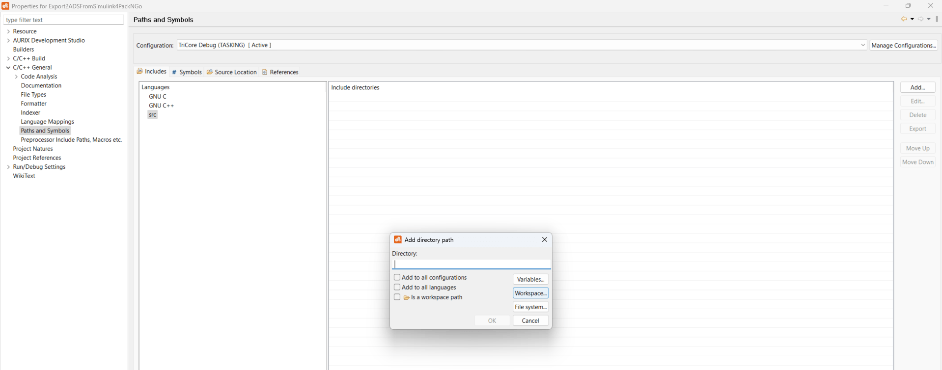
5. In the properties window, set these properties for the IDE to fetch the declaration header files and source implementation files of the generated code.
Navigate to C/C++ General > Paths and Symbols, add the AlgorithmExportToADS2_ert_rtw folder in the Includes tab.
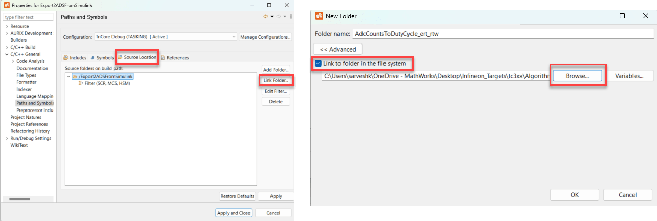
In the Source Location tab, click link folder. In the New Folder dialog box, select Link to folder in the file system and click Browse to select the AlgorithmExportToADS2_ert_rtw folder.
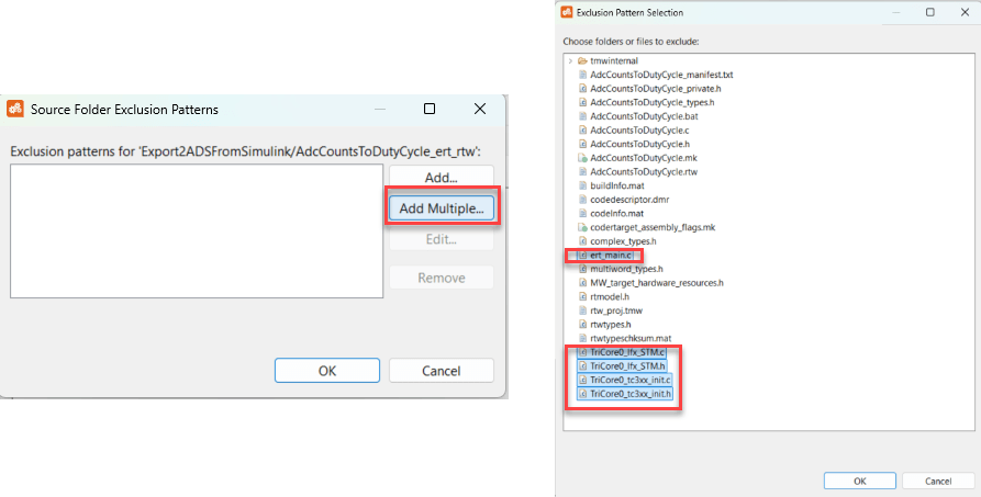
After adding the AlgorithmExportToADS2_ert_rtw folder in Source Location tab, double-click the folder to customize the folder exclusion pattern. Click Add Multiple > Select
ert_main.c,TriCore0_Ifx_STM.c,TriCore0_Ifx_STM.h,TriCore0_tc3xx_init.c, andTriCore0_tc3xx_init.c> click OK. This step excludes these files from the build process because this example shows the implementation only for the step functionality of the model.
6. After setting properties, click Apply and Close.
Integrate Code, Build with ADS and Deploy to Hardware
Copy these supporting files provided with this example to the ADS project for code integration.
1. ADC_Single_Channel.h declares two functions initEVADC and readEVADC.
2. ADC_Single_Channel.c defines two functions initEVADC and readEVADC.
initEVADCinitializes the EVADC as a single channel and configures the pin AN0. The ADC uses 3.3 volts as the reference voltage.readEVADCfunction reads the result from pin AN0 and outputs the result as a 12-bit value.
3. GTM_ATOM_1PH.h declares two functions initGtmAtom1ph and updateGtmAtom1phDuty.
4. GTM_ATOM_1PH.c defines two functions initGtmAtom1ph and updateGtmAtom1phDuty.
initGtmAtom1phgenerates PWM signal of 100 Hz on five channels, namely 0, 1, 2, 3, 4. The fourth channel is configured to Port 0 Pin 5, which is connected to the LED in active-low configuration.updateGtmAtom1phDutyreceives a floating point input and updates the duty cycle on the fourth channel of the PWM signal that is connected to the LED.
5. Update the code in the Cpu0_Main.c file of the ADS project to include and use the supporting files and the generated code files imported from Simulink.
These images show snippets of code from the updated Cpu0_Main.c file for two two code generation scenarios.
case (i) when the generated code uses the default storage class for inports and outports.
case (ii) when the generated code uses the
ImportedExternandExportedGlobalstorage class for the inports and outports, respectively.
6. After updating the code, build the code by clicking the Rebuild Active Project icon in the ADS toolbar.

7. After successfully building the code, ADS generates a HEX file in the TriCore Debug (TASKING) folder of the project.
8. Select the HEX file using the Aerix flasher to deploy the code to the microcontroller KIT that is connected to your PC via a micro-USB. To download the flasher tool, see Aurix Flasher tool.
9. After the code is deployed on the hardware, use a screwdriver to rotate the screw on the on-board potentiometer and observe the change in LED's intensity. The LED is bright when the duty cycle is low because it is connected in active-low configuration.