Implement HDL Optimized Modulo by Constant
This example shows how to use the Modulo by Constant HDL Optimized block.
The modulo operation,
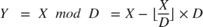
is an important building block for many mathematical algorithms. However, this formula is computationally inefficient for fixed-point and integer inputs. Many embedded processors lack instructions for integer division, and those with them require many clock cycles to compute. Division is also inefficient on commercially-available FPGAs, whose arithmetic circuits are optimized for multiplication, addition, and subtraction. Finally, for the fixed-point modulo operation, it is difficult to choose the data types used for the calculation because the division operation is unbounded.
While the generic modulo problem poses many challenges, we can simplify the problem if the denominator is a constant value. In this case, rewrite the division operation as

where  has enough precision that

and  is a function that computes the fractional part of its argument. All of the operations used in this formula are suitable for efficient FPGA deployment.
The following example shows how to use the Modulo by Constant HDL Optimized block to perform this operation and provides sample resource usage and performance statistics.
How to Use the Modulo by Constant HDL Optimized Block
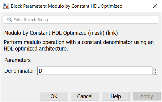
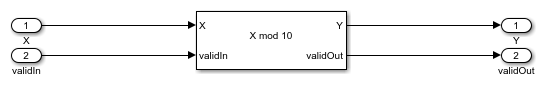
The Modulo by Constant HDL Optimized block requires you to specify the Denominator parameter, as shown below.
The block is shown below when Denominator is set to 10. The block icon displays both the mathematical expression for the modulo operation and the latency of the block. The block latency is 4 cycles for non-power of 2 denominators, and 0 cycles for power of 2 denominators.
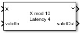
From the value of Denominator and the datatype of X, the block can compute all necessary constants and datatypes. Since it is designed for FPGA deployment, it uses the control signals validIn and validOut to indicate when X and Y are valid. Additionally, it simulates with the same latency as the generated HDL code.
To use the block, first create fixed-point input data. The format shown below is consumable by the From Workspace block.
Using the same format, create a boolean validIn signal that toggles from false to true repeatedly.
To finish setting up the data for the problem, set D equal to the constant denominator to use for the modulo operation.
Open the model.
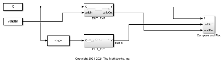
The subsystem DUT_FXP computes  for fixed-point inputs using the Modulo by Constant HDL Optimized block.
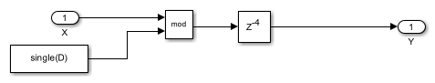
The subsystem DUT_FLT computes using a Math Function block with the Function parameter set to mod. Because the Simulink® mod operation only supports floating-point and integer inputs, the input data is cast to single precision before being input to the Math Function block. It additionally uses a delay block to match the latency of the subsystem DUT_FXP.
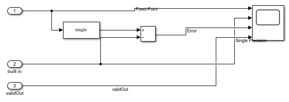
The subsystem Compare and Plot plots all outputs and computes the difference between the fixed-point computation and the floating-point ideal.
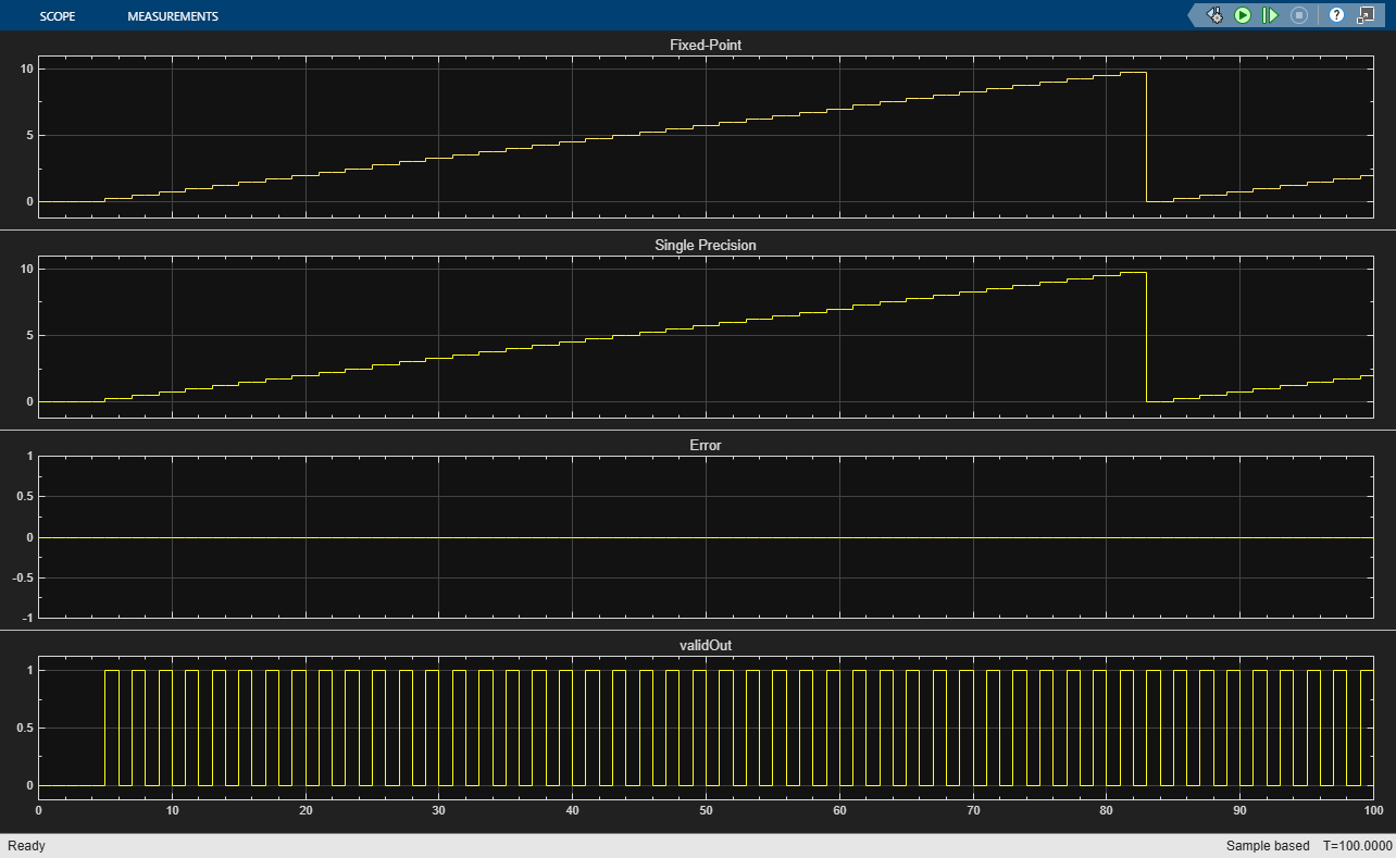
Simulate the model and examine the scope to compare the fixed-point and floating-point results.
The results from the Modulo by Constant HDL Optimized and Math Function blocks agree exactly, as the plot below shows. Note that there is a delay between the start of the simulation and the first time validOut goes high due to the latency in the system. This latency will be the same in the generated HDL code.
Generate HDL Code
If you have an HDL Coder™ license, you can generate and deploy HDL Code for the DUT_FXP subsystem as shown below.
makehdl('modulo_by_constant_block_example/DUT_FXP');
Implemented HDL Statistics
Sample statistics for resource usage on a Xilinx® Virtex®-7 XC7VX485 FFG1157-1 device are shown below. The implemented design is able to run at greater than 250MHz on this device.
       Resources       Usage
    _______________    _____

    LUT                 24
    Slice Registers     47
    DSP48               1