Air Traffic Control
This example shows how to generate an air traffic control scenario, simulate radar detections from an airport surveillance radar (ASR), and configure a global nearest neighbor (GNN) tracker to track the simulated targets using the radar detections. This enables you to evaluate different target scenarios, radar requirements, and tracker configurations without needing access to costly aircraft or equipment. This example covers the entire synthetic data workflow.
Air Traffic Control Scenario
Simulate an air traffic control (ATC) tower and moving targets in the scenario as platforms. Simulation of the motion of the platforms in the scenario is managed by trackingScenario.
Create a trackingScenario and add the ATC tower to the scenario.
% Create tracking scenario
scenario = trackingScenario(UpdateRate=0);
% Add a stationary platform to model the ATC tower
tower = platform(scenario);
Airport Surveillance Radar
Add an airport surveillance radar (ASR) to the ATC tower. A typical ATC tower has a radar mounted 15 meters above the ground. This radar scans mechanically in azimuth at a fixed rate to provide 360 degree coverage in the vicinity of the ATC tower. Common specifications for an ASR are listed:
Sensitivity: 0 dBsm @ 111 km
Mechanical Scan: Azimuth only
Mechanical Scan Rate: 12.5 RPM
Electronic Scan: None
Field of View: 1.4 deg azimuth, 10 deg elevation
Azimuth Resolution: 1.4 deg
Range Resolution: 135 m
Model the ASR with the above specifications using the fusionRadarSensor.
rpm = 12.5;
fov = [1.4;10];
scanrate = rpm*360/60;  % deg/s
updaterate = scanrate/fov(1); % Hz

radar = fusionRadarSensor(1,"Rotator", ...
    UpdateRate = updaterate, ...           % Hz
    FieldOfView = fov, ...                 % [az;el] deg
    MaxAzimuthScanRate = scanrate, ...     % deg/sec
    AzimuthResolution = fov(1), ...        % deg
    ReferenceRange = 111e3, ...            % m
    ReferenceRCS = 0, ...                  % dBsm
    RangeResolution = 135, ...             % m
    HasElevation=true, ...                 % Enable elevation measurement
    HasRangeRate=true, ...                 %
    RangeRateLimits=[-300 300], ...
    FalseAlarmRate=1e-7, ...
    DetectionCoordinates = 'Sensor spherical');

% Mount radar at the top of the tower
radar.MountingLocation = [0 0 -15];
tower.Sensors = radar;
Tilt the radar so that it surveys a region beginning at 2 degrees above the horizon. To do this, enable elevation and set the mechanical scan limits to span the radar's elevation field of view beginning at 2 degrees above the horizon. Because trackingScenario uses a North-East-Down (NED) coordinate frame, negative elevations correspond to points above the horizon.
% Set mechanical elevation scan to begin at 2 degrees above the horizon
elFov = fov(2);
tilt = 2; % deg
radar.MechanicalElevationLimits = [-fov(2) 0]-tilt; % deg
Set the elevation field of view to be slightly larger than the elevation spanned by the scan limits. This prevents raster scanning in elevation and tilts the radar to point in the middle of the elevation scan limits.
radar.FieldOfView(2) = elFov+1e-3;
The fusionRadarSensor models range and elevation bias due to atmospheric refraction. These biases become more pronounced at lower altitudes and for targets at long ranges. Because the index of refraction changes (decreases) with altitude, the radar signals propagate along a curved path. This results in the radar observing targets at altitudes which are higher than their true altitude and at ranges beyond their line-of-sight range.
Add three airliners within the ATC control sector. One airliner approaches the ATC from a long range, another departs, and the third is flying tangential to the tower. Model the motion of these airliners over a 60 second interval.
trackingScenario uses a North-East-Down (NED) coordinate frame. When defining the waypoints for the airliners below, the z-coordinate corresponds to down, so heights above the ground are set to negative values.
% Duration of scenario
sceneDuration = 60; % s
scenario.StopTime = sceneDuration;

% Inbound airliner
ht = 3e3;
spd = 900*1e3/3600; % m/s
wp = [-5e3 -40e3 -ht;-5e3 -40e3+spd*sceneDuration -ht];
traj = waypointTrajectory('Waypoints',wp,'TimeOfArrival',[0 sceneDuration]);
platform(scenario,'Trajectory', traj);

% Outbound airliner
ht = 4e3;
spd = 700*1e3/3600; % m/s
wp = [20e3 10e3 -ht;20e3+spd*sceneDuration 10e3 -ht];
traj = waypointTrajectory('Waypoints',wp,'TimeOfArrival',[0 sceneDuration]);
platform(scenario,'Trajectory', traj);

% Tangential airliner
ht = 4e3;
spd = 300*1e3/3600; % m/s
wp = [-20e3 -spd*sceneDuration/2 -ht;-20e3 spd*sceneDuration/2 -ht];
traj = waypointTrajectory('Waypoints',wp,'TimeOfArrival',[0 sceneDuration]);
platform(scenario,'Trajectory', traj);
GNN Tracker
A global nearest neighbor (GNN) tracker is a multi-target tracker that uses a global optimization to assign sensor data from all targets to the estimated target states, called tracks. In this example, you use a task-oriented GNN tracker, because the task-oriented tracker allows you to easily specify the target type and sensor type you want to use. Doing so simplifies the tracker tuning. The following steps show how to create a task-oriented GNN tracker using the steps shown in the following diagram.
Specify Aircraft Type
The first step in defining the tracker requires specifying the types of objects you want to track. In this example, the objects are aircraft flying near Logan airport, which are mostly jet-powered passenger aircraft. Use the trackerTargetSpec function to create a target specification for a passenger aircraft and observe the properties of the specification.
passengerSpec = trackerTargetSpec("aerospace","aircraft","passenger");
disp(passengerSpec)
  PassengerAircraft with properties:

           MaxHorizontalSpeed: 250    m/s
             MaxVerticalSpeed: 20     m/s
    MaxHorizontalAcceleration: 10     m/s²
      MaxVerticalAcceleration: 1      m/s²
The passenger aircraft target specification defines typical speeds and accelerations in the horizontal and vertical planes for a passenger aircraft. The speeds are used to define a prior distribution for a constant velocity model while the accelerations are used to define the process noise of the constant velocity model. This is all taken care of by the spec, when it integrates with the tracker shown below. In the passenger aircraft case, the speeds and accelerations represent a typical passenger jet flying at common cruise speeds. You can use this specification for tracking any passenger jet-propelled aircraft, including business jets. The speeds and accelerations are tunable and can be modified to fit specific aircraft type.
Specify Sensor Types
After specifying what you want to track, you must specify the sensors you use for tracking. In this example, you use the airport primary surveillance radar, which is a monostatic rotating radar that scans the sky as it rotates. Use the trackerSensorSpec function to create the monostatic radar specification for the airport surveillance radar and observe its properties.
activeRadarSpec = trackerSensorSpec("aerospace","radar","monostatic")
activeRadarSpec =
  AerospaceMonostaticRadar with properties:

           MaxNumLooksPerUpdate: 30
    MaxNumMeasurementsPerUpdate: 10

    IsPlatformStationary: 1
        PlatformPosition: [0 0 0]         m
     PlatformOrientation: [3⨯3 double]
        MountingLocation: [0 0 0]         m
          MountingAngles: [0 0 0]         deg

       HasElevation: 1
       HasRangeRate: 1
        FieldOfView: [60 20]       deg
        RangeLimits: [0 1e+05]     m
    RangeRateLimits: [-500 500]    m/s

      AzimuthResolution: 1      deg
        RangeResolution: 100    m
    ElevationResolution: 5      deg
    RangeRateResolution: 10     m/s

    DetectionProbability: 0.9
          FalseAlarmRate: 1e-06
You can divide the radar properties into the following broad categories:
Properties related to how the radar operates and how it reports to the tracker, for example
MaxNumLooksPerUpdate,IsPlatformStationary,PlatformPosition, etc. These properties must be specified using information from the radar operator, for example Logan airport.Properties related to the radar measurement information, for example
HasElevation,FieldOfView,RangeLimits,etc. These properties are specified by the radar manufacturer for a specific radar mode in use and can be found on a radar spec sheet.
Use the following code to define the Logan airport surveillance radar. The radar reports its measurements to the tracker once every two seconds.
towerPosition = [0 0 0];
activeRadarSpec.MaxNumLooksPerUpdate = ceil(360/radar.FieldOfView(1)); % Defines the number of looks to complete a 360 degrees scan.
activeRadarSpec.MaxNumMeasurementsPerUpdate = 20;
activeRadarSpec.PlatformPosition = towerPosition;
activeRadarSpec.PlatformOrientation = eye(3);
The following lines of code ensure that the properties of the radar specification match the equivalent properties of the scenario radar.
activeRadarSpec.MountingLocation = radar.MountingLocation;
activeRadarSpec.MountingAngles = radar.MountingAngles;
activeRadarSpec.HasElevation = radar.HasElevation;
activeRadarSpec.HasRangeRate = radar.HasRangeRate;
activeRadarSpec.FieldOfView = radar.FieldOfView;
activeRadarSpec.RangeLimits = radar.RangeLimits;
activeRadarSpec.RangeRateLimits = radar.RangeRateLimits;
activeRadarSpec.AzimuthResolution = radar.AzimuthResolution;
activeRadarSpec.RangeResolution = radar.RangeResolution;
activeRadarSpec.ElevationResolution = radar.ElevationResolution;
activeRadarSpec.RangeRateResolution = radar.RangeRateResolution;
activeRadarSpec.DetectionProbability = radar.DetectionProbability;
activeRadarSpec.FalseAlarmRate = radar.FalseAlarmRate;
Configure Tracker to Use Target and Sensor Specifications
The last step in specifying the tracker is to configure it to use the target and sensor specifications you defined earlier. To create the GNN tracker, you choose "gnn" as the algorithm type.
tracker = multiSensorTargetTracker(passengerSpec,activeRadarSpec,"gnn");Using the target specifications, the tracker configures the right motion and object survival models. Using the sensor specifications, the tracker configures the right observability, measurement, clutter, birth, and state initialization models. This is all done within the tracker and does not require additional tuning. Note that all the target and sensor specification properties are tunable.
disp(tracker)
  fusion.tracker.GNNHistoryTracker with properties:

         TargetSpecifications: {[1×1 PassengerAircraft]}
         SensorSpecifications: {[1×1 AerospaceMonostaticRadar]}
       MaxMahalanobisDistance: 5
    NumUpdatesForConfirmation: [2 3]
         NumMissesForDeletion: [5 5]
tracker.NumMissesForDeletion = [2 2]; % Probability of detection is high, so you can use a more aggressive deletion threshold.
tracker.MaxMahalanobisDistance = 15;
Understand Sensor Data Format
The sensor specification allows you to pass sensor data into the tracker and acts as an interpreter between the sensor data and the tracker. To understand this point better, display the data format for the active radar spec.
dataFormat(activeRadarSpec)
ans = struct with fields:
             LookTime: [0 0 0 0 0 0 0 0 0 0 0 0 0 0 0 0 0 0 0 0 0 0 0 0 0 0 0 0 0 0 0 0 0 0 0 0 0 0 0 0 0 0 0 0 0 0 0 0 0 0 0 0 0 0 0 0 0 0 0 0 0 0 0 0 0 0 0 0 0 0 0 0 0 0 0 0 0 0 0 0 0 0 0 0 0 0 0 0 0 0 0 0 0 0 0 0 0 0 0 0 0 0 0 0 0 0 … ] (1×258 double)
          LookAzimuth: [0 0 0 0 0 0 0 0 0 0 0 0 0 0 0 0 0 0 0 0 0 0 0 0 0 0 0 0 0 0 0 0 0 0 0 0 0 0 0 0 0 0 0 0 0 0 0 0 0 0 0 0 0 0 0 0 0 0 0 0 0 0 0 0 0 0 0 0 0 0 0 0 0 0 0 0 0 0 0 0 0 0 0 0 0 0 0 0 0 0 0 0 0 0 0 0 0 0 0 0 0 0 0 0 0 0 … ] (1×258 double)
        LookElevation: [0 0 0 0 0 0 0 0 0 0 0 0 0 0 0 0 0 0 0 0 0 0 0 0 0 0 0 0 0 0 0 0 0 0 0 0 0 0 0 0 0 0 0 0 0 0 0 0 0 0 0 0 0 0 0 0 0 0 0 0 0 0 0 0 0 0 0 0 0 0 0 0 0 0 0 0 0 0 0 0 0 0 0 0 0 0 0 0 0 0 0 0 0 0 0 0 0 0 0 0 0 0 0 0 0 0 … ] (1×258 double)
        DetectionTime: [0 0 0 0 0 0 0 0 0 0 0 0 0 0 0 0 0 0 0 0]
              Azimuth: [0 0 0 0 0 0 0 0 0 0 0 0 0 0 0 0 0 0 0 0]
            Elevation: [0 0 0 0 0 0 0 0 0 0 0 0 0 0 0 0 0 0 0 0]
                Range: [0 0 0 0 0 0 0 0 0 0 0 0 0 0 0 0 0 0 0 0]
            RangeRate: [0 0 0 0 0 0 0 0 0 0 0 0 0 0 0 0 0 0 0 0]
      AzimuthAccuracy: [0 0 0 0 0 0 0 0 0 0 0 0 0 0 0 0 0 0 0 0]
    ElevationAccuracy: [0 0 0 0 0 0 0 0 0 0 0 0 0 0 0 0 0 0 0 0]
        RangeAccuracy: [0 0 0 0 0 0 0 0 0 0 0 0 0 0 0 0 0 0 0 0]
    RangeRateAccuracy: [0 0 0 0 0 0 0 0 0 0 0 0 0 0 0 0 0 0 0 0]
The active radar data format includes all the information needed to understand the sensor scanning and measurements. The LookTime, LookAzimuth, and LookElevation fields provide information about the sensor beam azimuth and elevation angles as a function of time. Each of these fields contains as many zeros as the MaxNumLooksPerUpdate property of the active radar specification. When populating the struct with your sensor data, these fields are variable sized and you can pass only the number of elements that you need, for example, [0 0.1 0.2] for time.
The rest of the fields provide information about the sensor detections: their time, measurement, and measurement accuracy. The measurement and measurement accuracy are further split into azimuth, elevation, range, and range rate. Furthermore, the number of zeros in each of these fields is equal to the MaxNumMeasurementsPerUpdate property and you use them as variable sized.
The next line loads sensor data that was recorded in the radar data format. In this example, there is only one sensor, but sensorData is provided as a cell, because in the general case the tracker can use more than one sensor. To recreate the data, uncomment the line below, but note that it may take a considerable amount of time to run.
load("ATCSensorData.mat","sensorData");
% sensorData = helperRecordSensorData(scenario);
Visualize on a Map
You use trackingGlobeViewer to visualize the results on top of a map display. You position the origin of the local North-East-Down (NED) coordinate system used by the tower radar and tracker at the position of Logan airport in Boston. The origin is located at 42.366978 latitude and -71.022362 longitude and 50 meters above the sea level.
origin = [42.366978, -71.022362, 50];
mapViewer = trackingGlobeViewer('ReferenceLocation',origin,...
    'Basemap','streets-dark');
campos(mapViewer, origin + [0 0 1e5]);
drawnow;
restart(scenario);
plotScenario(mapViewer,scenario);
snapshot(mapViewer);

Track Airliners
In this section, you track the airliners using the recorded data and the tracker defined above.
You can define how much time passes between tracker updates using the control below. The helperSplitSensorData and helperSavePlatformPoses functions split the sensor and truth poses data based on this interval. Use an interval of 0.1 seconds for best snapshots of the tracking, if you want to capture snapshots.
radarDataInterval = 0.1; % In seconds. Use 0.1 seconds for the example snapshots.
radarDataForPlotting = helperSplitSensorData(sensorData,scenario.StopTime,radarDataInterval);
platformPoses = helperSavePlatformPoses(scenario,radarDataInterval);
numScanInds = round(60/12.5/radarDataInterval); % Number of scan indices it takes to complete a 360 degrees scan, which is used to clear the radar detections from the previous scan.
The following code resets the globe display and some utilities related to generating the snapshots.
% Save visualization snapshots for each scan
allsnaps = {};
clear(mapViewer);
plotPlatform(mapViewer,[scenario.Platforms{2:end}],TrajectoryMode="Full");
clear plotActiveRadarData;
clear snapPlotTrack;
Similarly, reset the tracker before the beginning of the scenario.
reset(tracker);
The following loop updates the tracker and the globe display.
for ind = 1:numel(radarDataForPlotting)
    % Update the tracker with the radar data
    tracks = tracker(radarDataForPlotting(ind));

    % Visualize tracks and platforms
    plotPlatform(mapViewer,platformPoses(:,ind));

    % Visualize data and tracks (helper)
    scanComplete = mod(ind,numScanInds)==0;
    plotActiveRadarData(mapViewer, activeRadarSpec,radarDataForPlotting(ind),NewScan=scanComplete);

    % Plot the trackss and take snapshots when needed.
    time = ind*radarDataInterval;
    allsnaps = snapPlotTrack(mapViewer,tracks,time,allsnaps);
end

% Take a final snapshot at the end of the scenario.
allsnaps = [allsnaps, {snapshot(mapViewer)}];
Show the first snapshot taken as the radar completes its first scan. The figure below shows the platform positions in white and the radar detections as light blue dots. At this point, the tracker has already been updated by all the detections up to this time. Internally, the tracker has initialized tracks for each of the detected airliners. These tracks are still tentative, and therefore the tracker has not returned them. Once the tracker promotes the tracks to confirmed, meeting the tracker's confirmation requirement of 2 hits out of 3 updates, these tracks will be shown.
figure
imshow(allsnaps{1});
The next two snapshots focus on the outbound airliner north of Boston. The first figure shows the immediately before updating the track dispaly and the second picture immediately after updating the track display. The detection in the top figure is used to update and confirm the initialized track from the previous scan's detection for this airliner. The next figure shows the confirmed track's position and velocity. The uncertainty of the track's position estimate is shown as the yellow ellipse. After only two detections, the tracker has established an accurate estimate of the outbound airliner's position and velocity. The airliner's true altitude is 4 km and it is traveling north at 700 km/hr.
figure
imshow(allsnaps{2});
figure
imshow(allsnaps{3});
The next couple of figures depic the state of the track right before and right after the third update. The first figure shows the state of the coasting track. Notice how the track's uncertainty has grown since it was updated in the previous figure. The second figure shows the track immediately after its update with the detection. You notice that the uncertainty of the track position is reduced after the update. The track uncertainty grows between updates and is reduced whenever it is updated with a new measurement. You also observe that after the third update, the track lies on top of the airliner's true position, indicating a very good estimate.
figure
imshow(allsnaps{5});
figure
imshow(allsnaps{7});
The final figure shows the state of all three airliners' tracks at the end of the scenario. There is exactly one track for each of the three airliners. The same track numbers are assigned to each of the airliners for the entire duration of the scenario, indicating that none of these tracks were dropped during the scenario.
figure
imshow(allsnaps{8});
The following table further highlights that the track estimates closely match the true altitude, heading and speed of the airliners.
truthTrackTable = tabulateData(scenario, tracks) %#ok<NOPTS>truthTrackTable=3×4 table
"T1" 4000 3958 90 89 700 698
"T2" 4000 4036 0 0 300 312
"T3" 3000 3138 0 359 900 905
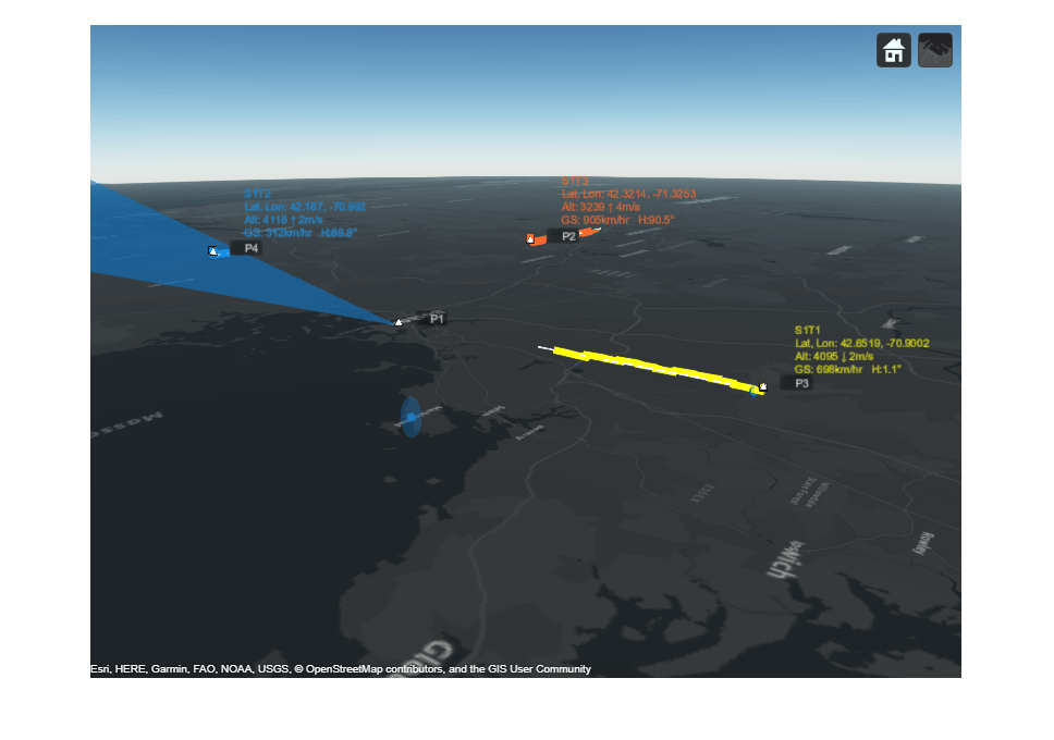
Visualize tracks in 3-D to get a better sense of the estimated altitudes.
% Reposition and orient the camera to show the 3-D nature of the map
camPosition = origin + [0.367, 0.495, 1.5e4];
camOrientation = [235, -17, 0]; % Looking south west, 17 degrees below the horizon
campos(mapViewer, camPosition);
camorient(mapViewer, camOrientation);
drawnow
The figure below shows a 3-D map of the scenario. You can see the simulated jets in white triangles with their trajectories depicted as white lines. The radar beam is shown as a blue cone with blue dots representing radar detections. The tracks are shown in yellow, orange, and blue and their information is listed in their respective color. Due to the nature of the 3-D display, some of the markers may be hidden behind others.
You can use the following controls on the map to get different views of the scene:
To pan the map, you left click on the mouse and drag the map.
To rotate the map, while holding the ctrl button, you left click on the mouse and drag the map.
To zoom the map in and out, you use the mouse scroll wheel.
snapshot(mapViewer);
Summary
This example shows how to generate an air traffic control scenario, simulate radar detections from an airport surveillance radar (ASR), and configure a global nearest neighbor (GNN) tracker to track the simulated targets using the radar detections. In this example, you learned how the tracker's history based logic promotes tracks. You also learned how the track uncertainty grows when a track is coasted and is reduced when the track is updated by a new detection.
Supporting Functions
tabulateData
This function returns a table comparing the ground truth and tracks.
function truthTrackTable = tabulateData(scenario, tracks)
% Process truth data
platforms = scenario.Platforms(2:end); % Platform 1 is the radar
numPlats = numel(platforms);
numTrks = numel(tracks);
truePos = zeros(numPlats,3);
trueAlt = zeros(numPlats,1);
trueSpd = zeros(numPlats,1);
trueHea = zeros(numPlats,1);
for i = 1:numPlats
    traj = platforms{i}.Trajectory;
    waypoints = traj.Waypoints;
    times = traj.TimeOfArrival;
    truePos(i,:) = waypoints(end,:);
    trueAlt(i) = -waypoints(end,3);
    trueVel = (waypoints(end,:) - waypoints(end-1,:)) / (times(end)-times(end-1));
    trueSpd(i) = norm(trueVel) * 3600 / 1000; % Convert to km/h
    trueHea(i) = atan2d(trueVel(1),trueVel(2));
end
trueHea = mod(trueHea,360);

% Associate tracks with targets
trackStates = [tracks.State];
trackPos = trackStates([1 3 5],:)';
euclideanDist = zeros(numPlats,numTrks);
for i = 1:numPlats
    for j = 1:numTrks
        euclideanDist(i,j) = norm(truePos(i,:)-trackPos(j,:));
    end
end
tgtID = matchpairs(euclideanDist,1000);
tgtInds = tgtID(tgtID(:,2),1);

% Process tracks assuming a constant velocity model
estAlt = zeros(numTrks,1);
estSpd = zeros(numTrks,1);
estHea = zeros(numTrks,1);
truthTrack = zeros(numTrks,7);
for i = 1:numTrks
    estAlt(i) = -round(tracks(i).State(5));
    estSpd(i) = round(norm(tracks(i).State(2:2:6)) * 3600 / 1000); % Convert to km/h;
    estHea(i) = round(atan2d(tracks(i).State(2),tracks(i).State(4)));
    estHea(i) = mod(estHea(i),360);
    platID = tgtInds(i);
    truthTrack(i,:) = [tracks(i).TrackID, trueAlt(platID), estAlt(i), trueHea(platID), estHea(i), ...
        trueSpd(platID), estSpd(i)];
end

% Organize the data in a table
names = {'TrackID','TrueAlt','EstimatedAlt','TrueHea','EstimatedHea','TrueSpd','EstimatedSpd'};
truthTrackTable = array2table(truthTrack,'VariableNames',names);
truthTrackTable = mergevars(truthTrackTable, (6:7), 'NewVariableName', 'Speed', 'MergeAsTable', true);
truthTrackTable.(6).Properties.VariableNames = {'True','Estimated'};
truthTrackTable = mergevars(truthTrackTable, (4:5), 'NewVariableName', 'Heading', 'MergeAsTable', true);
truthTrackTable.(4).Properties.VariableNames = {'True','Estimated'};
truthTrackTable = mergevars(truthTrackTable, (2:3), 'NewVariableName', 'Altitude', 'MergeAsTable', true);
truthTrackTable.(2).Properties.VariableNames = {'True','Estimated'};
truthTrackTable.TrackID = "T" + string(truthTrackTable.TrackID);
end
helperRecordSensorData - A helper to record sensor data from the scenario
function sensorData = helperRecordSensorData(scenario) %#ok<DEFNU>
if isa(scenario,"trackingScenarioRecording")
    recording = scenario.RecordedData; % We only need the struct
elseif isa(scenario,"struct")
    recording = scenario;
elseif isa(scenario,"trackingScenario") || isa(scenario,"radarScenario")
    seed = 2024; % Change this value if you want a different random number generator seed.
    disp("Recording the scenario to get sensor data. This may take several minutes.");
    recording = record(scenario,"Rotmat",IncludeSensors=true,RecordingFormat="struct",InitialSeed=seed);
else
    error("This example utility function can only be used with a trackingScenario a trackingScenarioRecording");
end

if ~isfield(recording,"SensorConfigurations") || ~isfield(recording,"Detections")
    error("Scenario recording must contain sensor configurations and detections to record sensor data");
end
% Assume all steps have the same sensors.
sensors = recording(1).SensorConfigurations;
detBuffer = vertcat(recording.Detections);
for i = 1:numel(recording)
    for j = 1:numel(recording(i).SensorConfigurations)
        recording(i).SensorConfigurations(j).Time = recording(i).SimulationTime;
    end
end
configBuffer = reshape([recording.SensorConfigurations],[],1);
sensorData = cell(1,numel(sensors));
for k = 1:numel(sensors)
    sensor = sensors(k);
    sensorIdx = sensor.SensorIndex;
    sensorMountingAngles =  rotmat(recording(1).CoverageConfig(k).Orientation,"frame");

    detSensorIndex = cellfun(@(x)x.SensorIndex,detBuffer);
    dets = detBuffer(detSensorIndex == sensorIdx);

    cfgSensorIndex = arrayfun(@(x)x.SensorIndex, configBuffer);
    cfgs = configBuffer(cfgSensorIndex == sensorIdx);
    if sensor.MeasurementParameters.HasRange
        sensorData{k} = recordMonostaticData(sensorMountingAngles, dets, cfgs);
    else
        sensorData{k} = recordESMData(sensorMountingAngles, dets, cfgs);
    end
end
end

function activeRadarData = recordMonostaticData(sensorMountingAngles, detections, cfgs)
% Reported config information
lookMountRot = cell(numel(cfgs),1);
for i = 1:numel(cfgs)
    if cfgs(i).MeasurementParameters(1).IsParentToChild
        lookMountRot{i} = cfgs(i).MeasurementParameters(1).Orientation;
    else
        lookMountRot{i} = cfgs(i).MeasurementParameters(1).Orientation';
    end
end
beamRot = cellfun(@(x)x*sensorMountingAngles',lookMountRot,UniformOutput=false);
ypr = cellfun(@(x)fusion.internal.frames.rotmat2ypr(x,"degrees"),beamRot,UniformOutput=false);
lookTime = arrayfun(@(x)x.Time,cfgs);
lookAzimuth = cellfun(@(x)x(1),ypr);
lookElevation = cellfun(@(x)-x(2),ypr);

% Reported measurement information
detectionTime = cellfun(@(x)x.Time,detections);
azimuth = cellfun(@(x)x.Measurement(1),detections);
elevation = cellfun(@(x)x.Measurement(2),detections);
range = cellfun(@(x)x.Measurement(3),detections);
rangeRate = cellfun(@(x)x.Measurement(4),detections);
azimuthAccuracy =  cellfun(@(x)x.MeasurementNoise(1,1),detections);
elevationAccuracy =  cellfun(@(x)x.MeasurementNoise(2,2),detections);
rangeAccuracy =  cellfun(@(x)x.MeasurementNoise(3,3),detections);
rangeRateAccuracy =  cellfun(@(x)x.MeasurementNoise(4,4),detections);

activeRadarData = struct(LookTime=lookTime(:)',LookAzimuth=lookAzimuth(:)', ...
    LookElevation=lookElevation(:)', DetectionTime=detectionTime(:)', ...
    Azimuth=azimuth(:)',Elevation=elevation(:)', Range=range(:)', ...
    RangeRate=rangeRate(:)',AzimuthAccuracy=sqrt(azimuthAccuracy(:)'), ...
    ElevationAccuracy=sqrt(elevationAccuracy(:)'),RangeAccuracy=sqrt(rangeAccuracy(:)'), ...
    RangeRateAccuracy=sqrt(rangeRateAccuracy(:)'));
end

function esmData = recordESMData(sensorMountingAngles, detections, cfgs)
% Reported config information
lookMountRot = cell(numel(cfgs),1);
for i = 1:numel(cfgs)
    if cfgs(i).MeasurementParameters(1).IsParentToChild
        lookMountRot{i} = cfgs(i).MeasurementParameters(1).Orientation;
    else
        lookMountRot{i} = cfgs(i).MeasurementParameters(1).Orientation';
    end
end
beamRot = cellfun(@(x)x*sensorMountingAngles',lookMountRot,UniformOutput=false);
ypr = cellfun(@(x)fusion.internal.frames.rotmat2ypr(x,"degrees"),beamRot,UniformOutput=false);
lookAzimuth = cellfun(@(x)x(1),ypr);
lookElevation = cellfun(@(x)-x(2),ypr);
lookTime = arrayfun(@(x)x.Time,cfgs);

detectionTime = cellfun(@(x)x.Time,detections);
azimuth = cellfun(@(x)x.Measurement(1),detections);
elevation = cellfun(@(x)x.Measurement(2),detections);
azimuthAccuracy =  cellfun(@(x)x.MeasurementNoise(1,1),detections);
elevationAccuracy =  cellfun(@(x)x.MeasurementNoise(2,2),detections);

esmData = struct(LookTime=lookTime(:)',LookAzimuth=lookAzimuth(:)', ...
    LookElevation=lookElevation(:)',DetectionTime=detectionTime(:)', ...
    Azimuth=azimuth(:)',Elevation=elevation(:)',AzimuthAccuracy=sqrt(azimuthAccuracy(:)'), ...
    ElevationAccuracy=sqrt(elevationAccuracy(:)'));
end
helperSplitSensorData - A helper to split recorded sensor data to the tracker update interval
function varargout=helperSplitSensorData(sensorData,stopTime,trackerInterval)
varargout = cell(1,nargout);
if iscell(sensorData)
    varargout = cellfun(@(s) splitOneSensorData(s,stopTime,trackerInterval), sensorData, UniformOutput=false);
else
    varargout{1} = splitOneSensorData(sensorData,stopTime,trackerInterval);
end
end

function data=splitOneSensorData(sensorData,stopTime,trackerInterval)
frameTime = 0;
ind = 1;
numFrames = ceil(stopTime/trackerInterval);
data = repmat(sensorData,numFrames,1);
while frameTime < stopTime
    withinInterval = sensorData.LookTime >= frameTime & sensorData.LookTime < frameTime+trackerInterval;
    data(ind).LookTime = sensorData.LookTime(withinInterval);
    data(ind).LookAzimuth = sensorData.LookAzimuth(withinInterval);
    data(ind).LookElevation = sensorData.LookElevation(withinInterval);
    withinInterval = sensorData.DetectionTime >=frameTime & sensorData.DetectionTime < frameTime+trackerInterval;
    data(ind).DetectionTime = sensorData.DetectionTime(withinInterval);
    if isfield(sensorData,"Azimuth")
        data(ind).Azimuth = sensorData.Azimuth(1,withinInterval);
        data(ind).AzimuthAccuracy = sensorData.AzimuthAccuracy(1,withinInterval);
    end
    if isfield(sensorData,"Elevation")
        data(ind).Elevation = sensorData.Elevation(1,withinInterval);
        data(ind).ElevationAccuracy = sensorData.ElevationAccuracy(1,withinInterval);
    end
    if isfield(sensorData,"Range")
        data(ind).Range = sensorData.Range(1,withinInterval);
        data(ind).RangeAccuracy = sensorData.RangeAccuracy(1,withinInterval);
    end
    if isfield(sensorData,"RangeRate")
        data(ind).RangeRate = sensorData.RangeRate(1,withinInterval);
        data(ind).RangeRateAccuracy = sensorData.RangeRateAccuracy(1,withinInterval);
    end
    if isfield(sensorData,"TargetIndex")
        data(ind).TargetIndex = sensorData.TargetIndex(1,withinInterval);
    end
    frameTime = frameTime + trackerInterval;
    ind = ind + 1;
end
end
helperSavePlatformPoses - Record platform poses at tracker update timestamps
function platformPoses = helperSavePlatformPoses(scenario,trackerInterval)
endind = ceil(scenario.StopTime/trackerInterval);
samplePose = struct(PlatformID=1,ClassID=0,Position=zeros(1,3),Velocity=zeros(1,3),Acceleration=zeros(1,3),Orientation=eye(3),AngularVelocity=zeros(1,3));
platformPoses = repmat(samplePose,numel(scenario.Platforms),endind);
sampleTimes = trackerInterval*(1:endind);

for p = 1:numel(scenario.Platforms)
    thisPlatform = scenario.Platforms{p};
    trajectory = thisPlatform.Trajectory;
    if isa(trajectory,"waypointTrajectory")
        [position,orientation,velocity,acceleration,angularVelocity] = lookupPose(trajectory,sampleTimes);
        orientation = rotmat(orientation,"frame");
        for i = 1:endind
            platformPoses(p,i) = struct(PlatformID=thisPlatform.PlatformID,ClassID=thisPlatform.ClassID, ...
                Position=position(i,:),Velocity=velocity(i,:),Acceleration=acceleration(i,:), ...
                Orientation=orientation(:,:,i),AngularVelocity=angularVelocity(i,:));
        end
    else % Assumes that non waypointTrajectory means stationary object
        platformPoses(p,:) = repmat(struct(PlatformID=thisPlatform.PlatformID,ClassID=thisPlatform.ClassID, ...
            Position=thisPlatform.Position,Velocity=zeros(1,3),Acceleration=zeros(1,3),Orientation=thisPlatform.Orientation, ...
            AngularVelocity=zeros(1,3)),1,endind);
    end
end
end