Hydraulic Actuator Control: Verification from Requirements to HDL Implementation
This example presents a workflow that applies Model-Based Design to implement and verify a hydraulic actuator control. The workflow starts with requirements, creates test harnesses and test suites, generates HDL code, and then verifies that code. Using HDL Verifier™ and Simulink® verification and validation tools, the example shows how:
Cosimulation enables direct reuse of the Model-Based Design testing.
SV-DPI generation enables exporting testbench components to a downstream SystemVerilog or UVM design verification environment.
A Model-Based Design Workflow
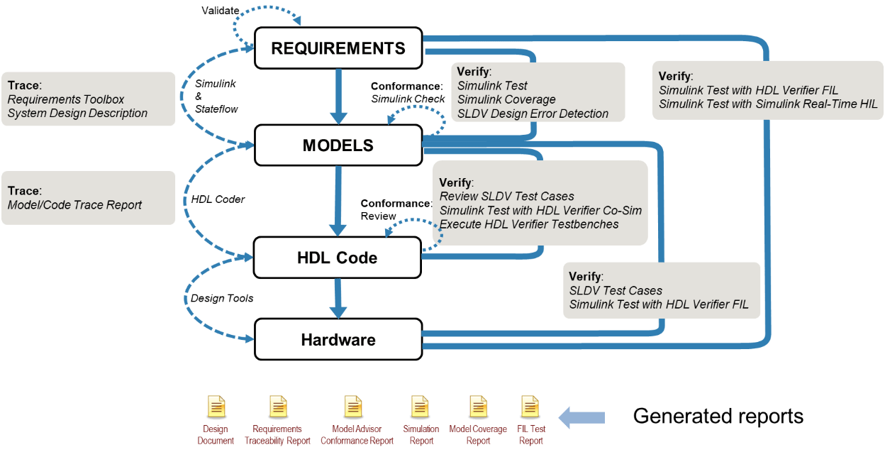
A top-down model-based design workflow from requirements to FPGA implementation is shown below. This example will elaborate on the HDL verification steps using HDL Verifier in conjunction with the Simulink Validation & Verification tools.
Running Steps in Example Sections
Each section provides guidance about the products you need to perform its activities. Given the high number of products involved, most steps present different levels of engagement in case you do not have those tools or do not want to spend the time executing them. Each step may include:
Actions that are central to the purpose of this example are presented as Live Editor commands and can be executed by the document "run" buttons. These provide output in-line with the commands.
% This is an example of a command runnable using the Live Editor "Run"
disp("An example command.")
Actions that are important but secondary to the purpose of this example are presented as code examples. If desired, these can be highlighted and executed using right-click menu "Evaluate selection..." or using F9.
% This is an example of a command runnable by highlighting + F9
disp("Another example of a command.")
Pre generated reports and artifacts are presented as hyperlinks. If you do not have the required products or do not want to execute them to save time, you can click on these links.
Open Top-Level Example Project
Open the top-level project in order to set up paths and open sub-projects.
open('HDLVTopProject/HDLVTopProject.prj');Define System and Hardware Requirements
Use system and hardware requirements to develop a system architecture. You can review these requirements to check the compliance of your design with requirements standards. They become the basis of test development and coverage points during verification.
Product Requirement:
Requirements Toolbox™
Project Files:
02_Requirements\specification\HelicopterSystemRequirements.slreqx02_Requirements\specification\HelicopterHardwareRequirements.slreqx02_Requirements\specification\documents\HelicopterSystemRequirements_ReqReport.pdf02_Requirements\specification\documents\HelicopterHardwareRequirements_ReqReport.pdf
Generate Requirements Reports
Requirements Toolbox captures requirements and generates reports. The system requirements report provides traceability from the system-level requirements to the system model and hardware requirements set. The hardware requirements report provides traceability from the hardware requirements to the design model and back to the system-level requirements set. The linkage between the requirements and the execution of tests ensures coverage of the requirements during the course of the workflow.
You can select + F9 to open requirements sets and generate reports:
% Open and generate a system requirements report:
open('HelicopterSystemRequirements.slreqx');
genReqReport('HelicopterSystemRequirements','pdf');
% Open and generate a hardware requirements report:
open('HelicopterHardwareRequirements.slreqx');
genReqReport('HelicopterHardwareRequirements','pdf');
You can view pre-generated reports:
Dynamically Test Actuator Control Loop
Verify the hardware design in Simulink by using simulation.
Product Requirements:
System Composer™
Simulink Test™
Simulink Coverage™
Simscape™ Fluids™
Project Files:
03_ConceptualDesign\ActuatorLoop\test_cases\ActuatorControlLoop.slx03_ConceptualDesign\ActuatorLoop\test_cases\ActLoopTest.mldatx03_ConceptualDesign\ActuatorLoop\verification_results\simulation_tests\ActLoopTest_Report.pdf03_ConceptualDesign\ActuatorLoop\verification_results\model_coverages\ActuatorLoop_cov.html
Open Model
This example uses model ActuatorControlLoop.slx, a model that consists of:
Actuator (plant model)
Command input
Controller
Position output
% Open system model (requires System Composer)
open_system('ActuatorControlLoop');
Review Test Cases and Procedures
Use the Test Manager in Simulink Test to implement test cases and procedures. In this example, Simulink test file ActLoopTest.mldatx runs model ActuatorControlLoop.slx and verifies the proper operation of the model using these test cases:
Chirp frequency response from 0 to 100Hz
Small signal positive step
Small signal negative step
Large signal positive step
Large signal positive step
% Open test file (requires Simulink Test)
open('ActLoopTest.mldatx');
Run Test Procedure
Run the simulation test procedure for the Actuator Control Loop and generate reports.
Note: Expect the chirp frequency response test to fail because the model does not meet the minimum bandwidth requirement.
% Run the simulation tests (requires Simulink Test)
bdclose('all');
runActuatorSim;
Simulink Test generates a test report for the five simulation cases that includes:
A pass/fail summary for the aggregated test results
The pass/fail outcome for each test case
The description for each test case
Links to requirements being verified for each test case (trace data)
Plots of the simulation results for each test case
You can view the pre-generated report:
Review System Design Report
The model serves as a hardware conceptual design. Generate a report to describe the design and establish traceability to the hardware requirements by using Simulink Report Generator™. Its System Design Description (SDD) report provides a complete description of the model, including:
Snapshots of the model at the root level and subsystems
Interfaces for the model at the root level and subsystems
Block execution order
Block setting details
Model parameter details
Configuration setting details
Traceability between the model objects and requirements documents
Glossary and report explanation
% Open the model and generate the SDD report
open_ActuatorLoop;
genSDD('ActuatorLoop');
If you do not have Simulink Report Generator, view a pre-generated report:
Hardware Design Verification of ActuatorLoop (Static and Dynamic Verification)
Verify the hardware design of the model by using both static testing (inspection and analysis) and dynamic testing (simulation).
For more information, see:
Product Requirements:
Simulink Check™
Simulink Design Verifier™
Simulink Test
Simulink Coverage
Project Files:
03_ConceptualDesign\ActuatorLoop\specification\ActuatorLoop.slx03_ConceptualDesign\ActuatorLoop\verification_results\design_standard_checks\ActuatorLoop_SMS_Conformance_Report.pdf03_ConceptualDesign\ActuatorLoop\verification_results\design_error_detections\design_error\ActuatorLoop_Design_Error_Detection_Report.pdf03_ConceptualDesign\ActuatorLoop\test_cases\ActuatorLoop_REQ_Based_Test.mldatx03_ConceptualDesign\ActuatorLoop\specification\ActuatorLoop_Harness_HLR.slx03_ConceptualDesign\ActuatorLoop\verification_results\simulation_tests\ActuatorLoop_REQ_Based_Test_Report.pdf03_ConceptualDesign\ActuatorLoop\verification_results\model_coverages\ActuatorLoop_REQ_Based_Model_Coverage_Report.html
Run Model Advisor Checks for Static Verification
The Model Advisor allows you to check a model for conformance to standards, accuracy and consistency, verifiability, as well as compatibility with other MathWorks® tools. In this example, a configuration file provides compatibility checks for HDL Coder™ code generation and high-integrity modeling guidelines. When you run a check analysis, the Model Advisor generates a report that indicates the pass status for each check.Run the checks on the model.
% Execute the checks and generate the Model Advisor report (requires Simulink Check)
checkModelStds('ActuatorLoop');
If you do not have Simulink Check, view the pre-generated report:
Run Design Error Detection for Static Verification
Identify errors related to safety and find any unused functions. by using design error detection in Simulink Design Verifier to check a model for these potential design errors:
Dead logic
Integer overflow
Division by zero
Violation of specified intermediate minimum and maximum values
Out of bound array access
When you run an analysis, Simulink Design Verifier generates a report that provides information about the flagged design errors.
Run design error detection on the model.
% Run the design error detection analysis and generate the report (requires Simulink Design Verifier)
detectDesignErrs('ActuatorLoop');
If you do not have Simulink Design Verifier, view the pre-generated report:
Note: The report contains some undecided objectives.
Run Model Simulation for Functional Verification
Verify that the design complies with the hardware requirements by running the model as an executable specification. In this example, ActuatorLoop.slx implements the hardware design of the actuator control algorithm. A benefit of using the Model-Based Design approach is that you can verify the conceptual design against the hardware requirements through simulation, without first developing the actual hardware.
Review Test Cases and Procedures
Implement test cases and procedures by using the Test Manager in Simulink Test. Simulink Test executes the tests as described in ActuatorLoop_REQ_Based_Test.mldatx by running the test harness model ActuatorLoop_Harness_HLR.slx. A test suite verifies the proper operation of the model by using these test cases:
Positive feedback signal test.
Negative feedback signal test.
Positive command signal test.
Negative command signal test.
Positive ramp command signal test.
Negative ramp command signal test.
Positive command and negative feedback signal test.
Negative command and positive feedback signal test.
open('ActuatorLoop_REQ_Based_Test.mldatx'); % Open test file (requires Simulink Test)
bdclose('all');                             % Close any open models
open_system('ActuatorLoop_Harness_HLR');    % Open the test harness
Run Test Procedure
bdclose('all');                   % Close any open models
verifyModel2Reqs('ActuatorLoop'); % Run the simulation tests (requires Simulink Test)
Simulink Test runs the test suite and generates a test report for the simulation test cases that includes:
Pass/fail summary for the aggregated test results
Summary of the aggregated model coverage results
Pass/fail outcome for each test case
Description for each test case
Links to requirements that are being verified for each test case (trace data)
Plots of the simulation results for each test case
The results also include a report that summarizes the model coverage achieved by the simulation tests. Model coverage is calculated with Simulink Coverage.
If you do not have Simulink Test, view the pre-generated reports:
Open the pre-generated test report — Simulation test results
Open the pre-generated, requirements-based model coverage report — Summary coverage report
Generate VHDL Code
With your hardware and system designs verified, now you can generate VHDL® code for the ActuatorLoop.slx model.
Product Requirements:
HDL Coder
Project Files:
03_ConceptualDesign\ActuatorLoop\specification\ActuatorLoop.slx04_DetailedDesign\specification\ActuatorLoop\ActuatorLoop_Industry_report.html04_DetailedDesign\specification\ActuatorLoop\html\ActuatorLoop_codegen_rpt.html04_DetailedDesign\specification\ActuatorLoop\<generated code.vhdlfiles>
Use HDL Coder to generate code for the ActuatorLoop model and subsystems as register-transfer level (RTL) hardware description language (HDL). The code generator is configured to satisfy the industry standards for VHDL code. For more information, see Industry standards for the ActuatorLoop.
genHdlCode('ActuatorLoop');
If you do not have HDL Coder, view the pre-generated code generation reports for the ActuatorLoop and its subsystem:
Note: The name of the model-level file violates the naming convention rule and the report flags it accordingly. All other rules pass.
Manually review the HDL code for compliance of the detailed design with hardware requirements and the conceptual design, as well as traceability between the model and hardware requirements. HDL coder generates traceability between the model and hardware requirements by adding trace tags to the comments in the generated code files as comments.
Implementation of the final FPGA or ASIC is done using applicable third party tools from the HDL code. To assist in the final hardware design process and optimize the design, HDL Coder allows you to define the third party tool and the target hardware device.
Verify HDL with Cosimulation
Verify the generated VHDL using HDL Verifier and cosimulation. With cosimulation, an HDL Cosimulation block replaces the part the design used for HDL code generation. The model reuses test suites and test harnesses from your previous Simulink Test work.
Product Requirements:
HDL Coder
Simulink Test
HDL Verifier
Third-party HDL simulation tool (ModelSim/Questa™ shown)
Project Files:
03_ConceptualDesign\ActuatorLoop\specification\ActuatorLoop.slx04_DetailedDesign\test_cases\ActuatorLoop\HDL_Cosim\ActuatorLoop_Harness_CoSim.slx04_DetailedDesign\test_cases\ActuatorLoop\HDL_Cosim\ActuatorLoop_CoSim_Test.mldatx03_ConceptualDesign\ActuatorLoop\specification\ActuatorLoop_Harness_HLR.slx04_DetailedDesign\test_cases\ActuatorLoop\HDL_CoSim\test bench folders
Set up the HDL simulator for use in cosimulation. The following is a MathWorks-specific setup. You must update the setupHDLSimulationTool function to reflect your own environment.
edit("setupHDLSimulationTool"); % update this function to reflect your own environment
setupHDLSimulationTool;
Generate an HDL co-simulation harness for the ActuatorLoop model that includes a ModelSim block with VHDL code by using test harness ActuatorLoop_Harness_CoSim.slx. This script:
Clones and exports the high-level requirements harness used previously for functional verification.
Generate VHDL code for the ActuatorLoop design under test.
Generate an HDL cosimulation testbench and block using HDL Verifier.
Copy the HDL cosimulation block into the new harness model.
genCosimHarness('ActuatorLoop_Harness_HLR', 'ActuatorLoop', 'ActuatorLoop_Harness_CoSim', codeType='VHDL');
A Simulink test file with the same test suite used for functional verification earlier is used for running against the HDL implementation. Test callbacks specify how to compile the HDL code and launch the HDL simulator for each test. Examine the harness and test suite.
bdclose('all');                                   % Close any open models
open_system('ActuatorLoop_Harness_CoSim');        % Open the test harness
open('ActuatorLoop_CoSim_Test.mldatx');           % Open the test file (requires Simulink Test)
Run the test suite and generate a Simulink Test report and create code coverage data from the HDL simulator.
bdclose('all');                                   % Close any open models
verifyWithCosimHarness('ActuatorLoop');           % Run the co-simulation tests
Merge the HDL code coverage data for each test using HDL simulator utilities and compare them against the model coverage from Simulink Test.
compareCoverage('ActuatorLoop', tbType='HDL_Cosim');
If you do not have Simulink Test or an HDL simulator, view the pre-generated report for the ActuatorLoop cosimulation results:
Other Techniques for HDL Verification
Using Simulink Test, HDL Coder, and HDL Verifier to manage the development of the verification suite in a top-down model-based design workflow allows for a stream-lined workflow to iterate until design closure. Testing holes discovered in the model coverage can be leveraged to improve the initial HDL coverage. Testing holes found in the HDL cosimulations can likewise be brought back to improve the source model testing.
However, sometimes a hand-off is required to downstream HDL implementation and HDL design verification teams that are unable to run Simulink and its toolboxes. This independence might be for running regressions or for extending testing in their native environments.
HDL Coder and HDL Verifier can aid in this hand-off process in several ways. Three ways are shown in this example.
Export a Vector-Based HDL Test Bench
Another option for verification of the VHDL is to create an HDL Test Bench that can be executed outside of the Simulink environment. With this method, the original Simulink harness and test suite is run in order to capture data values on the design interface and saving them as hexadecimal values in .dat files. A completely independent, stand-alone HDL testbench can then read the input values from .dat files, apply them to the generated HDL, then read the expected output values from .dat files and compare against the actual results.
Product Requirements:
HDL Coder
Third-party HDL simulator tool (ModelSim/Questa shown)
Relevant Project Files:
03_ConceptualDesign\ActuatorLoop\specification\ActuatorLoop_Harness_HLR.slx04_DetailedDesign\test_cases\ActuatorLoop\HDL_TB\test bench folders
Generate an HDL test bench for the ActuatorLoop model from the test harness ActuatorLoop_Harness_HLR.slx. This script calls makehdltb for the harness DUT, ActuatorLoop_Harness_HLR/ActuatorLoop. The makehdltb process:
Generates HDL code and report for the ActuatorLoop.
Generates Industry Compliance and Check reports.
Runs model simulations to capture inputs and expected results for all the Signal Editor scenarios and stores those in separate *.dat files.
Creates a testbench to run a vector-based HDL simulation of all of the *.dat files.
bdclose('all');                          % Close any open models
open_system('ActuatorLoop_Harness_HLR'); % Open the test harness
genHDLTestBench('ActuatorLoop_Harness_HLR', 'ActuatorLoop', codeType='VHDL');
If you do not have HDL Coder, the project includes pre-generated ActuatorLoop_tb.vhd and *.dat files for each scenario. Here are links to the first scenario:
Execute the vector-based HDL testbench for TestCase1-8. After all of the vectors have been applied, a "TEST COMPLETED (PASSED)" or "TEST COMPLETED (FAILED)" message is seen.
setupHDLSimulationTool;
verifyWithHDLTestBench('ActuatorLoop_Harness_HLR', 'ActuatorLoop');
Export a SystemVerilog DPI Component Testbench
An issue with the vector-based HDL testbench is that if there are a lot of inputs/outputs and/or the simulation time is very long, the number and size of .dat files can make the vector capture very inefficient. (A good example of such a system is a video processing pipeline operating on a 4K image stream.) Another option for verification of the VHDL is to create a SystemVerilog DPI-C Testbench that can be executed outside of the Simulink environment. For this testbench, instead of capturing vectors, a C-based model is created representing both the stimulus generation and design data processing. The C-model and the HDL module are integrated into a stand-alone SystemVerilog testbench. As the HDL simulation is run, the C-model generates expected outputs and the HDL testbench compares them against the HDL outputs.
Product Requirements:
HDL Coder
HDL Verifier and its support package, ASIC Testbench
Third-party HDL simulator tool (ModelSim/Questa shown)
Embedded Coder®
Project Files:
03_ConceptualDesign\ActuatorLoop\specification\ActuatorLoop_Harness_HLR.slx04_DetailedDesign\test_cases\ActuatorLoop\DPIC_TB\test bench folders
Generate a DPI-C test bench for the ActuatorLoop model by using test harness ActuatorLoop_Harness_HLR.slx. Because the generation for each scenario can take several minutes, use the scenarioList argument to limit the scope of the work. This script:
Iterates through the specified list of Signal Editor scenarios
Clones and exports the harness to a new model,
<ScenarioName>.slxSelects the given scenario in the Signal Editor block.
Calls the
makehdltbfunction to generate its outputs to separate project folders,04_DetailedDesign\test_cases\ActuatorLoop\DPIC_TB\TB1-TB8.The outputs include the HDL for the DUT; a C-code reference design of the model stimulus and DUT; a SystemVerilog testbench to simulate the HDL and reference design; Industry Compliance and Generation Check reports.
% Generate the SystemVerilog DPI testbench for only the first scenario.
bdclose('all');
open_system('ActuatorLoop_Harness_HLR');
genDPICTestBench('ActuatorLoop_Harness_HLR', 'ActuatorLoop', codeType='VHDL', scenarioList=1);
If you do not have the tools needed to generate the DPI-C test benches, the project includes pre-generated test bench code files for each scenario. Here is a link to the first scenario:
Execute the SystemVerilog-DPI testbench for TestCase1. The simulation displays a TEST COMPLETED (PASSED) or TEST COMPLETED (FAILED) message.
setupHDLSimulationTool;
verifyWithDPICTestBench('ActuatorLoop', scenarioList=1);
Export SystemVerilog and UVM Components and Testbenches
The previous methods were executing the same tests against the HDL as were run in Simulink Test. They proved equivalency between the Simulink representation of the design and the HDL representation. Commonly, it is required to extend testing further in the downstream implementation environment. For example, usually hardware-based data transfer protocols such as AXI or I2C are not modeled in Simulink and are only introduced later during the HDL implementation. In such cases, the Simulink test harness can be exported to a SystemVerilog-based or Universal Verification Methodology (UVM) -based testbench environment. A simulation to prove equivalency with the Simulink testing is done first, then the testbench can be extended to handle the additional protocol-based testing.
Product Requirements:
HDL Coder
HDL Verifier
ASIC Testbench
Third-party HDL simulator tool (ModelSim/Questa shown)
Embedded Coder
Project Files:
03_ConceptualDesign\ActuatorLoop\specification\ActuatorLoop_Harness_HLR.slx04_DetailedDesign\test_cases\ActuatorLoop\UVM_TB\testbench folders
Generate a UVM-compatible Simulink harness for the Actuator Loop model by executing the utility function exportHarness4UVM. It creates a new model ActuatorLoop_Harness_UVM.slx, from harness model ActuatorLoop_Harness_HLR.slx, that conforms to the necessary modularization for UVM generation such as placing the DUT model in a subsystem.
bdclose('all');
genUVMHarness('ActuatorLoop_Harness_HLR', 'ActuatorLoop', 'ActuatorLoop_UVM');
The exported UVM testbench is comprised of the subsystems: ActuatorLoop_DUT, Stimulus, and Scoreboard. Each of the subsystems is C-code generated and wrapped in the appropriate UVM component code. A separate UVM testbench is generated for each of the eight scenarios in the Signal Editor block in the harness and stored in separate project folders 04_DetailedDesign\test_cases\ActuatorLoop\UVM_TB\TB1 - TB8. Each scenario generated can take several minutes.
% Generate the UVM testbench for only the first scenario.
open_system('ActuatorLoop_UVM');
genUVMTestBench('ActuatorLoop', 'ActuatorLoop_UVM', 'Stimulus', 'ActuatorLoop_DUT', 'Scoreboard', scenarioList=1);
If you do not have the tools to generate the UVM testbenches, view the pre-generated testbench code files for each scenario, here is a link to the first scenario:
Execute the UVM testbench for the first scenario:
setupHDLSimulationTool;
verifyWithUVMTestBench('ActuatorLoop', scenarioList=1);
For the UVM testbench, both the HDL code coverage and the functional coverage from the model "verify" calls is gathered. Merge the HDL coverage results from all of the UVM testbench simulations and compare them with the Simulink model coverage obtained in Verify HDL with Cosimulation.
compareCoverage('ActuatorLoop', tbType='UVM_TB');
If you do not have Simulink Test or an HDL simulator, view the pre-generated report for the Actuator Control Loop UVM results for scenario 1:
Conclusion and Next Steps
This example showed a complete top-down Model-Based Design workflow from requirements to verification of an HDL implementation. Special emphasis was given to different HDL verification techniques including full Simulink Test test suite and test harness reuse through the use of the HDL Cosimulation block. Other capabilities including vector-based HDL testbench, a dynamic C-model based HDL testbench, and a fully extensible SystemVerilog-UVM testbench were also shown.
A whole portfolio of examples for HDL verification can be found in the Featured Examples list of the HDL Verifier product.
See Also
Topics
- Hydraulic Actuator Control: A Model-Based Design Example Using HDL Coder and HDL Verifier (DO Qualification Kit)
- Helicopter Flight Control: A Model-Based Design Example for DO-178C and DO-331 (DO Qualification Kit)