Visually Compare Simulink Signals with HDL Signals
Tutorial: Overview
Note
This tutorial and the tool used are specific to ModelSim™ users; however, much of the process will be the same for Xcelium™ users with a similar tool. See HDL simulator documentation for details.
VCD files include data that can be graphically displayed or analyzed with
post-processing tools. An example of such a tool is the ModelSim
vcd2wlf tool, which converts a VCD file to a WLF file that you
can then view in a ModelSim
wave window. This tutorial shows how you might apply the
vcd2wlf tool.
Tutorial: Instructions
This tutorial uses the model from the Manchester Receiver (Absolute Time Mode) example. Perform the following steps to view VCD data:
Place a copy of the Manchester Receiver Simulink® example model
abs_manchestermodel.slxin a writable folder.Open your writable copy of the Manchester Receiver model. On the Simulation tab, in the File section, click Open. Select the file
abs_manchestermodeland click Open. The Simulink model should appear as follows. The HDL Cosimulation block is marked "VHDL Manchester Receiver".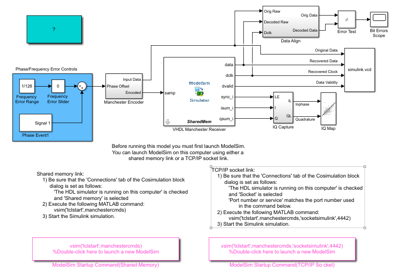
Do not follow the numbered steps in the Manchester Receiver model. Follow only the steps provided in this tutorial.
Open the Library Browser.
Replace the Signal Scope block with a To VCD File block, as follows:
Delete the Signal Scope block. The lines representing the signal connections to that block change to dashed lines, indicating the disconnection.
Find and open the HDL Verifier™ block library.
Click "For Use with Siemens® ModelSim" to access the HDL Verifier Simulink blocks for use with ModelSim.
Copy the To VCD File block from the Library Browser to the model by clicking the block and dragging it from the browser to the location in your model window previously occupied by the Signal Scope block.
Double-click the To VCD File block icon. The Block Parameters dialog box appears.
Type
MyVCDfile.vcdin the VCD file name text box.Type
4in the Number of input ports text box.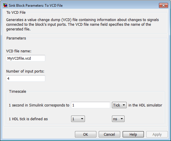
Click OK. Simulink applies the new parameters to the block.
Connect the signals
Original Data,Recovered Data,Recovered Clock, andData Validityto the block ports. The following display highlights the modified area of the model.
Save the model.
Select the following command line from the instructional text that appears in the demonstration model:
vsim('tclstart',manchestercmds,'socketsimulink',4442)Paste the command in the MATLAB® Command Window and execute the command line. This command starts ModelSim and configures it for a Simulink cosimulation session.
Open the HDL Cosimulation block parameters dialog box and select the Connection tab. Change the Connection method to Socket and “4442” for the TCP/IP socket port. The port you specify here must match the value specified in the call to the
vsimcommand in the previous step.Start the simulation from the Simulink model window.
When the simulation is complete, locate, open, and browse through the generated VCD file,
MyVCDfile.vcd(any text editor will do).Close the VCD file.
Change your input focus to ModelSim and end the simulation.
Change the current folder to the folder containing the VCD file and enter the following command at the ModelSim command prompt:
vcd2wlf MyVCDfile.vcd MyVCDfile.wlf
The
vcd2wlfutility converts the VCD file to a WLF file that you display with the commandvsim -view.In ModelSim, open the wave file
MyVCDfile.wlfby entering the following command:vsim -view MyVCDfile.wlf
Display the waveforms with the following command:
add wave MyVCDfile:/*
A wave window appears showing the signals logged in the VCD file.
Click the Zoom Full button
 to view the signal data. The wave
window should appear as follows.
to view the signal data. The wave
window should appear as follows.
Exit the simulation. One way of exiting is to enter the following command:
dataset close MyVCDfile
ModelSim closes the data set, clears the wave window, and exits the simulation.
For more information on the vcd2wlf utility and working with
data sets, see the ModelSim documentation.