Contenu principal

Fan (G)

R2026b

Fan in gas network

  • Fan (G) block

Libraries:
Simscape / Fluids / Gas / Turbomachinery

Description

The Fan (G) block represents a fan in a gas network. You can model the torque and pressure gain over the fan as a function of static pressure and flow rate or by using 1D or 2D tabulated reference pressure, shaft speed, and flow rate data.

By default, flow and pressure gain are from port A to port B. Port C represents the fan casing, and port R represents the fan shaft. You can specify the normal operating shaft direction in the Mechanical orientation parameter. If the shaft begins to spin in the opposite direction, the pressure difference across the fan drops to zero.

Parameterization by Nominal Pressure, Flow Rate, and Shaft Speed

When you set the Fan parameterization parameter to Static pressure and flow rate at reference shaft speed, the block uses the analytical fan affinity laws and reference pressure differential to calculate the pressure gain from port A to port B:

pB−pA=Δpref(ωωref)2(DDref)2,

where:

  • Δpref is the reference pressure differential. The block uses a quadratic fit of the fan pressure differential values at the Maximum static pressure gain at zero flow, Nominal static pressure gain, and Maximum volumetric flow rate at zero pressure parameters.

  • ω is the shaft angular velocity, ωR – ωC.

  • ωref is the Reference shaft speed parameter.

  • DDref is the Fan diameter scale factor parameter.

The block calculates the shaft torque from the reference mechanical power and the fan affinity laws:

τ=Φrefω2ωref3(DDref)5.

Where Φref is the proportion of the pressure gain to the fan efficiency:

Φref=qrefΔprefηref.

When you set the Shaft power specification parameter to Fan efficiency, the block uses a quadratic fit of efficiency between the fan peak performance, ηnom, and 0. ηnom is equivalent to the Nominal efficiency parameter, which the block interprets as the peak efficiency. If you set the Shaft power specification parameter to Brake power, the block derives the nominal fan efficiency from the nominal brake power, Φnom, at peak or nominal conditions:

ηnom=qnomΔpnomΦnom.

The block assumes the efficiency is zero when there is no flow or when the flow reaches the maximum volumetric flow rate at zero pressure. The block uses the current flow q to compute the reference flow rate as:

qref=qωrefω(DrefD)3.

1-D Tabulated Data Parameterization: Pressure as a Function of Flow Rate at Reference Shaft Speed

When you set the Fan parameterization parameter to 1D tabulated data - static pressure vs. flow rate at reference shaft speed, you can model fan performance as a function of volumetric flow rate. The block interpolates the pressure gain from port A to port B from the 1-D Static pressure gain vector parameter, Δpref(qref):

pB−pA=Δpref(qref)(ρρref)(ωωref)2(DDref)2.

Here, ρ is the fluid density, and ρref is the reference density, which is equivalent to the Reference density parameter. The block calculates the shaft torque from the reference mechanical power and the fan affinity laws:

τ=Φref(qref)ω2ωref3(ρρref)(DDref)5,

where ρref is the Reference density.

The block uses the current flow q to compute the reference flow rate:

qref=qωrefω(DrefD)3.

When the simulation is outside the range of the provided tables, the block extrapolates pressure based on the average slope of the fan curves and the reference torque to the nearest point.

2-D Tabulated Data Parameterization: Pressure as a Function of Shaft Speed and Flow Rate

When you set the Fan parameterization parameter to 2D tabulated data - static pressure vs. shaft speed and flow rate, you can model fan performance as a 2-D function of volumetric flow rate and angular velocity. The block interpolates the pressure gain from port A to port B from the 2-D Static pressure gain table, dp(w,q) parameter. The block defines the reference pressure gain, Δpref(qref,ω), as

pB−pA=Δpref(qref,ω)(ρρref)(DDref)2.

The block calculates shaft torque from the reference mechanical power and the fan affinity laws:

τ=Φref(qref,ω)ω(ρρref)(DDref)5,

where the reference mechanical power is a function of the reference flow rate and the current shaft speed.

The block uses the current flow q to compute the reference flow rate:

qref=q(DrefD)3.

When the simulation is outside the range of the provided tables, the block extrapolates pressure based on the average slope of the fan curves and the reference torque to the nearest point.

Missing Data

If your table has unknown data points, use NaN in place of these values. The block fills in the NaN elements by extrapolating based on the average slope of the fan curves. Do not use artificial numeric values because these values distort fan behavior when operating in that region. When using unknown data:

  • The NaN elements in the table must be contiguous.

  • The positions of the NaN elements in the Static pressure gain table, dp(w,q), Efficiency table, eta(w,q), and Mechanical power table, W(w,q) parameters must match each other.

  • NaN elements must be located in the upper-right portion of the table, which corresponds to the highest volumetric flow rate and lowest shaft speed.

2-D Tabulated Data Parameterization: Flow Rate as a Function of Shaft Speed and Static Pressure

When you set the Fan parameterization parameter to 2D tabulated data - flow rate vs. shaft speed and static pressure, you can model the flow rate through the fan as a 2-D function of pressure and angular velocity. The volumetric flow rate is interpolated from the 2-D Volumetric flow rate table, q(w,dp) parameter, qref. The reference flow rate is a function of the reference pressure gain, Δpref, and the current shaft speed, ω:

q=qref(Δpref,ω)(DDref)3,

where the reference pressure gain derives from the pressure differential over the fan:

Δpref=(pB−pA)(ρrefρ)(DrefD)2.

The shaft torque derives from the reference mechanical power and the fan affinity laws:

τ=Φref(Δpref,ω)ω(ρρref)(DDref)5,

where the reference mechanical power is a function of the reference flow rate and the current shaft speed.

When the simulation is outside the range of the provided tables, the block extrapolates pressure based on the average slope of the fan curves and the reference torque to the nearest point.

Missing Data

If your table has unknown data points, use NaN in place of these values. The block fills in the NaN elements by extrapolating based on the average slope of the fan curves. Do not use artificial numeric values because these values distort fan behavior when operating in that region. When using unknown data:

  • The NaN elements in the table must be contiguous.

  • The positions of the NaN elements in the Volumetric flow rate table, q(w,dp), Efficiency table, eta(w,dp), and Mechanical power table, W(w,dp) parameters must match each other.

  • NaN elements must be located in the upper-right portion of the table, which corresponds to the highest volumetric flow rate and lowest shaft speed.

Power and Efficiency

You can specify shaft power by providing either fan efficiency or brake power.

The block calculates efficiency as

η=ΦfluidΦbrake,

where the brake power, or mechanical power measured at the shaft, is

Φbrake=τω.

The block calculates fluid power as

Φfluid=q(pB−pA).

The block calculates torque as

τ=Φbrakeω.

Visualizing the Fan Curve

You can check the parameterized fan performance by plotting the pressure, power, efficiency, and torque as a function of the flow. To generate a plot of the current fan settings, in the block dialog box, click the Plot button next to Fan characteristics. If you change settings or data, click Apply on the block parameters and click Reload Data on the fan curve figure.

The default block parameterization results in these plots:
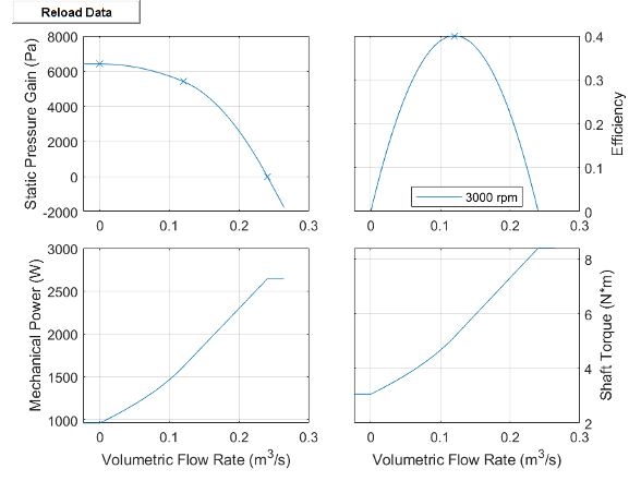
Plot of fan characteristic curves

Energy Balance

When you clear Model losses as heat transfer into fluid, the energy balance equation is

ϕA+ϕB+Phydro=0,

where:

  • ΦA is the energy flow rate at port A.

  • ΦB is the energy flow rate at port B.

The pump hydraulic power is a function of the pressure difference between pump ports,

Phydro=Δpm˙ρ.

When you select Model losses as heat transfer into fluid, the energy balance equation is

dpIdt∂U∂pI+dTIdt∂U∂TI=ϕA+ϕB+W˙mech+QH,

where:

  • QH is the heat flow rate into port H.

  • Ẇmech is the mechanical power.

  • U is the fluid volume internal energy.

  • pI is the fluid volume pressure.

  • TI is the fluid volume temperature.

The fluid density is constant, which is ensured by the equation

∂M∂pIdpIdt+∂M∂TIdTIdt=0,

where M is the mass of the fluid volume.

The block uses the Nominal temperature and Nominal pressure parameters to calculate the nominal density, which the block uses to approximate the fluid volume density.

Assumptions and Limitations

  • If the shaft rotates opposite to the specified mechanical orientation, the pressure difference across the block drops to zero and the results may not be accurate.

  • The block assumes that the fan is quasi-steady.

  • The block simulates fan performance in terms of static pressure rise, and not total fan pressure.

Examples
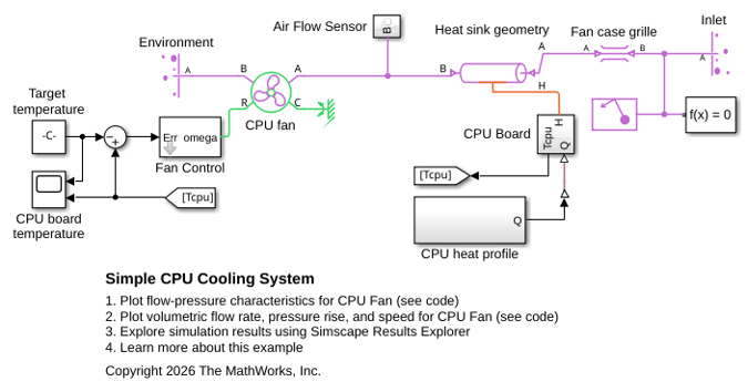
Ports

Conserving

expand all

Gas conserving port associated with the fluid.

Programmatic Use

Port: A

Gas conserving port associated with the fluid.

Programmatic Use

Port: B

Mechanical rotational conserving port associated with the shaft.

Programmatic Use

Port: R

Mechanical rotational conserving port associated with the casing.

Programmatic Use

Port: C

Thermal conserving port associated with the fluid volume.

Dependencies

To enable this port, select Model losses as heat transfer into fluid and Enable thermal port.

Programmatic Use

Port: H

Parameters

expand all

Performance

Fan performance model, specified as:

  • Static pressure and flow rate at reference shaft speed: Specify fan performance based on typical, nominal, or rated pressure gain and volumetric flow rate.

  • 1D tabulated data – static pressure vs flow rate at reference shaft speed: Specify fan performance based on interpolation of pressure gain data as a function of volumetric flow rate.

  • 2D tabulated data – static pressure vs shaft speed and flow rate: Specify fan performance based on the interpolation of pressure gain data as a function of shaft speed and volumetric flow rate.

  • 2D tabulated data – flow rate vs shaft speed and static pressure: Specify fan performance based on the interpolation of volumetric flow rate data as a function of shaft speed and pressure gain.

Programmatic Use

Parameter: fan_parameterization
Values: "fluids.gas.turbomachinery.enum.FanParameterization.Nominal" | "fluids.gas.turbomachinery.enum.FanParameterization.Table1D" | "fluids.gas.turbomachinery.enum.FanParameterization.Table2DPressure" | "fluids.gas.turbomachinery.enum.FanParameterization.Table2DFlowRate"

Fan power specification, specified as:

  • Fan efficiency: Derive the mechanical power from the fan efficiency.

  • Mechanical power: Specify the mechanical power directly.

Programmatic Use

Parameter: mechanical_power_spec
Values: "fluids.gas.turbomachinery.enum.FanMechanicalPowerSpec.Efficiency" | "fluids.gas.turbomachinery.enum.FanMechanicalPowerSpec.Power"

Volumetric flow rate through the fan at the reference shaft speed under nominal, typical, or rated operating conditions.

Dependencies

To enable this parameter, set Fan parameterization to Static pressure and flow rate at reference shaft speed.

Programmatic Use

Parameter: flow_rate_nominal

Pressure increase from port A to port B at the reference shaft speed under nominal, typical, or rated operating conditions.

Dependencies

To enable this parameter, set Fan parameterization to Static pressure and flow rate at reference shaft speed.

Programmatic Use

Parameter: pressure_nominal

Efficiency of converting the shaft power to fluid power at the reference shaft speed under nominal, typical, or rated operating conditions.

Dependencies

To enable this parameter, set:

  • Fan parameterization to Static pressure and flow rate at reference shaft speed.

  • Shaft power specification to Fan efficiency.

Programmatic Use

Parameter: eta_nominal

Mechanical power driving gas flow at the reference shaft speed under nominal, typical, or rated operating conditions.

Dependencies

To enable this parameter, set:

  • Fan parameterization to Static pressure and flow rate at reference shaft speed.

  • Shaft power specification to Brake power.

Programmatic Use

Parameter: power_nominal

Pressure increase from port A to port B at the reference shaft speed when there is no flow through the fan.

Dependencies

To enable this parameter, set Fan parameterization to Static pressure and flow rate at reference shaft speed.

Programmatic Use

Parameter: pressure_max

Free-delivery volumetric flow rate at the reference shaft speed and constant pressure.

Dependencies

To enable this parameter, set Fan parameterization to Static pressure and flow rate at reference shaft speed.

Programmatic Use

Parameter: flow_rate_max

Reference shaft angular velocity corresponding to the fan characteristic curve data.

Dependencies

To enable this parameter, set Fan parameterization to Static pressure and flow rate at reference shaft speed or 1D tabulated data - static pressure vs. flow rate at reference shaft speed.

Programmatic Use

Parameter: omega_ref_nominal

Parameter: omega_ref_1D

Threshold for the minimum shaft speed as a fraction of the reference shaft speed. The block uses this value to prevent the shaft speed from becoming zero and causing a division by zero error in the expression for qref.

Dependencies

To enable this parameter, set Fan parameterization to Static pressure and flow rate at reference shaft speed or 1D tabulated data - static pressure vs. flow rate at reference shaft speed.

Programmatic Use

Parameter: omega_threshold_factor

Vector of volumetric flow rate grid points for the 1-D interpolation of the fan characteristic curve. When Shaft power specification is Brake power, the fan data can extend beyond the normal operating region, and these values can be negative.

Dependencies

To enable this parameter, set Fan parameterization to 1D tabulated data - static pressure vs. flow rate at reference shaft speed.

Programmatic Use

Parameter: flow_rate_1D_TLU

Vector of pressure gain data points. Each element in the vector corresponds to an element in the Volumetric flow rate vector parameter. The pressure gain is the increase in pressure from port A to port B at the reference shaft speed. When Shaft power specification is Brake power, the fan data can extend beyond the normal operating region, and these values can be negative.

Dependencies

To enable this parameter, set Fan parameterization to 1D tabulated data - static pressure vs. flow rate at reference shaft speed.

Programmatic Use

Parameter: pressure_1D_TLU

Vector of fan efficiency data points. Each element in the vector corresponds to an element in the Volumetric flow rate vector parameter. The efficiency is the ratio of fluid power to shaft mechanical power at the reference shaft speed.

Dependencies

To enable this parameter, set Fan parameterization to 1D tabulated data - static pressure vs. flow rate at reference shaft speed and Shaft power specification to Fan efficiency.

Programmatic Use

Parameter: eta_1D_TLU

Vector of shaft mechanical power data points. Each element in the vector corresponds to an element in the Volumetric flow rate vector parameter. The mechanical power is the power that drives the fan at the reference shaft speed. These values can be negative if the fan data extends beyond the normal operating region.

Dependencies

To enable this parameter, set Fan parameterization to 1D tabulated data - static pressure vs. flow rate at reference shaft speed and Shaft power specification to Brake power.

Programmatic Use

Parameter: power_1D_TLU

Gas density for a given characteristic fan curve.

Dependencies

To enable this parameter, set Fan parameterization to 1D tabulated data - static pressure vs. flow rate at reference shaft speed, 2D tabulated data - static pressure vs. shaft speed and flow rate or 2D tabulated data - flow rate vs. shaft speed and static pressure.

Programmatic Use

Parameter: rho_ref_1D

Parameter: rho_ref_dp

Parameter: rho_ref_q

Vector of shaft angular velocity grid points for the 2-D interpolation of the fan characteristic curves.

Dependencies

To enable this parameter, set Fan parameterization to 2D tabulated data - static pressure vs. shaft speed and flow rate or 2D tabulated data - flow rate vs. shaft speed and static pressure.

Programmatic Use

Parameter: omega_dp_TLU

Parameter: omega_q_TLU

Vector of volumetric flow rate grid points for the 2-D interpolation of the fan characteristic curves. When Shaft power specification is Brake power, the fan data can extend beyond the normal operating region, and these values can be negative.

Dependencies

To enable this parameter, set Fan parameterization to 2D tabulated data - static pressure vs. shaft speed and flow rate.

Programmatic Use

Parameter: flow_rate_dp_TLU

M-by-N matrix of pressure gain data points for the 2-D interpolation of the pressure gain. The pressure gain is the increase in pressure from port A to port B. When Shaft power specification is Brake power, the fan data can extend beyond the normal operating region, and these values can be negative. M and N are the sizes of the corresponding vectors:

  • M is the number of elements in the Shaft speed vector, w parameter. The elements corresponding to zero flow rate must be in strictly ascending order.

  • N is the number of elements in the Volumetric flow rate vector, q parameter.

If your table has unknown data points, use NaN in place of these values. The block fills in the NaN elements by extrapolating based on the average slope of the fan curves. Do not use artificial numeric values because these values distort fan behavior when operating in that region. When using unknown data:

  • The NaN elements in the table must be contiguous.

  • The positions of the NaN elements in the Static pressure gain table, dp(w,q), Efficiency table, eta(w,q), and Mechanical power table, W(w,q) parameters must match each other.

  • NaN elements must be located in the upper-right portion of the table, which corresponds to the highest volumetric flow rate and lowest shaft speed.

Dependencies

To enable this parameter, set Fan parameterization to 2D tabulated data - static pressure vs. shaft speed and flow rate.

Programmatic Use

Parameter: pressure_dp_TLU

M-by-N matrix of efficiency data points for the 2-D interpolation of torque. The efficiency is the ratio of fluid power to shaft mechanical power. M and N are the sizes of the corresponding vectors:

  • M is the number of elements in the Shaft speed vector, w parameter.

  • N is the number of elements in the Volumetric flow rate vector, q parameter.

If your table has unknown data points, use NaN in place of these values. The block fills in the NaN elements by extrapolating based on the average slope of the fan curves. Do not use artificial numeric values because these values distort fan behavior when operating in that region. When using unknown data:

  • The NaN elements in the table must be contiguous.

  • The positions of the NaN elements in the Static pressure gain table, dp(w,q), Efficiency table, eta(w,q), and Mechanical power table, W(w,q) parameters must match each other.

  • NaN elements must be located in the upper-right portion of the table, which corresponds to the highest volumetric flow rate and lowest shaft speed.

Dependencies

To enable this parameter, set Fan parameterization to 2D tabulated data - static pressure vs. shaft speed and flow rate and Shaft power specification to Fan efficiency.

Programmatic Use

Parameter: eta_dp_TLU

M-by-N table of mechanical power data points for the 2-D interpolation of torque. These values can be negative if the fan data extends beyond the normal operating region. The mechanical power is the power that drives the fan. M and N are the sizes of the corresponding vectors:

  • M is the number of elements in the Shaft speed vector, w parameter. The elements corresponding to zero flow rate must be in strictly ascending order.

  • N is the number of elements in the Volumetric flow rate vector, q parameter.

If your table has unknown data points, use NaN in place of these values. The block fills in the NaN elements by extrapolating based on the average slope of the fan curves. Do not use artificial numeric values because these values distort fan behavior when operating in that region. When using unknown data:

  • The NaN elements in the table must be contiguous.

  • The positions of the NaN elements in the Static pressure gain table, dp(w,q), Efficiency table, eta(w,q), and Mechanical power table, W(w,q) parameters must match each other.

  • NaN elements must be located in the upper-right portion of the table, which corresponds to the highest volumetric flow rate and lowest shaft speed.

Dependencies

To enable this parameter, set Fan parameterization to 2D tabulated data - static pressure vs. shaft speed and flow rate and Shaft power specification to Brake power.

Programmatic Use

Parameter: power_dp_TLU

Vector of pressure gain grid points for the 2-D interpolation of the fan characteristic curves. When Shaft power specification is Brake power, the fan data can extend beyond the normal operating region, and these values can be negative.

Dependencies

To enable this parameter, set Fan parameterization to 2D tabulated data - flow rate vs. shaft speed and static pressure.

Programmatic Use

Parameter: pressure_q_TLU

M-by-N matrix of volumetric flow rate data points for the 2-D interpolation of volumetric flow rate. When Shaft power specification is Brake power, the fan data can extend beyond the normal operating region, and these values can be negative. M and N are the sizes of the corresponding vectors:

  • M is the number of elements in the Shaft speed vector, w parameter. The elements corresponding to zero flow rate must be in strictly ascending order.

  • N is the number of elements in the Static pressure gain vector, dp parameter.

If your table has unknown data points, use NaN in place of these values. The block fills in the NaN elements by extrapolating based on the average slope of the fan curves. Do not use artificial numeric values because these values distort fan behavior when operating in that region. When using unknown data:

  • The NaN elements in the table must be contiguous.

  • The positions of the NaN elements in the Volumetric flow rate table, q(w,dp), Efficiency table, eta(w,dp), and Mechanical power table, W(w,dp) parameters must match each other.

  • NaN elements must be located in the upper-right portion of the table, which corresponds to the highest volumetric flow rate and lowest shaft speed.

Dependencies

To enable this parameter, set Fan parameterization to 2D tabulated data - flow rate vs. shaft speed and static pressure.

Programmatic Use

Parameter: flow_rate_q_TLU

M-by-N matrix of efficiency data points for the 2-D interpolation of torque. The efficiency is the ratio of fluid power to shaft mechanical power. M and N are the sizes of the corresponding vectors:

  • M is the number of elements in the Shaft speed vector, w parameter.

  • N is the number of elements in the Static pressure gain vector, dp parameter.

If your table has unknown data points, use NaN in place of these values. The block fills in the NaN elements by extrapolating based on the average slope of the fan curves. Do not use artificial numeric values because these values distort fan behavior when operating in that region. When using unknown data:

  • The NaN elements in the table must be contiguous.

  • The positions of the NaN elements in the Volumetric flow rate table, q(w,dp), Efficiency table, eta(w,dp), and Mechanical power table, W(w,dp) parameters must match each other.

  • NaN elements must be located in the upper-right portion of the table, which corresponds to the highest volumetric flow rate and lowest shaft speed.

Dependencies

To enable this parameter, set Fan parameterization to 2D tabulated data - flow rate vs. shaft speed and static pressure and Shaft power specification to Fan efficiency.

Programmatic Use

Parameter: eta_q_TLU

M-by-N matrix of mechanical power data points for the 2-D interpolation of torque. These values can be negative if the fan data extends beyond the normal operating region. The mechanical power is the power that drives the fan. M and N are the sizes of the corresponding vectors:

  • M is the number of elements in the Shaft speed vector, w parameter. The elements corresponding to zero flow rate must be in strictly ascending order.

  • N is the number of elements in the Static pressure gain vector, dp parameter.

If your table has unknown data points, use NaN in place of these values. The block fills in the NaN elements by extrapolating based on the average slope of the fan curves. Do not use artificial numerical values because these values distort fan behavior when operating in that region. When using unknown data:

  • The NaN elements in the table must be contiguous.

  • The positions of the NaN elements in the Volumetric flow rate table, q(w,dp), Efficiency table, eta(w,dp), and Mechanical power table, W(w,dp) parameters must match each other.

  • NaN elements must be located in the upper-right portion of the table, which corresponds to the highest volumetric flow rate and lowest shaft speed.

Dependencies

To enable this parameter, set Fan parameterization to 2D tabulated data - flow rate vs. shaft speed and static pressure and Shaft power specification to Brake power.

Programmatic Use

Parameter: power_q_TLU

Geometric scale factor to increase or decrease the size of the simulated fan from the given fan parameterization. The scaling may not be accurate for scale factors much larger or much smaller than 1.

Programmatic Use

Parameter: diameter_ratio

Normal operating shaft direction. By default, flow and pressure gain are from port A to port B.

Programmatic Use

Parameter: mech_orientation
Values: "fluids.gas.turbomachinery.enum.FanMechanicalOrientation.Positive" | "fluids.gas.turbomachinery.enum.FanMechanicalOrientation.Negative"

Cross-sectional area of the gas flow at the fan inlet.

Programmatic Use

Parameter: area_A

Cross-sectional area of the gas flow at the fan outlet.

Programmatic Use

Parameter: area_B

Thermal Effects

Option to model heat transfer into the fluid. If you clear this parameter, losses from the conversion from mechanical power to fluid power dissipate to the environment. If you select this parameter, the block models these losses as heat transferred into the fluid.

Programmatic Use

Parameter: model_losses_into_fluid
Values: "true" | "false"

Volume of the gas in the fan.

Dependencies

To enable this parameter, select Model losses as heat transfer into fluid.

Programmatic Use

Parameter: volume

Temperature in the fluid volume at the start of simulation.

Dependencies

To enable this parameter, select Model losses as heat transfer into fluid.

Programmatic Use

Parameter: T_init

Priority that the solver assigns to the Initial temperature parameter when initializing the block.

Set this parameter to High to define your initial conditions. Set this parameter to Low or None if this initial condition conflicts with the initial conditions of another block.

Dependencies

To enable this parameter, select Model losses as heat transfer into fluid.

Programmatic Use

Parameter: T_init_priority
Values: "foundation.enum.Priority.High" | "foundation.enum.Priority.Low" | "foundation.enum.Priority.None"

Pressure in the fluid volume at nominal operating conditions.

Dependencies

To enable this parameter, select Model losses as heat transfer into fluid.

Programmatic Use

Parameter: p_nominal

Temperature in the fluid volume at nominal operating conditions.

Dependencies

To enable this parameter, select Model losses as heat transfer into fluid.

Programmatic Use

Parameter: T_nominal

Option to model the thermal port associated with the fluid volume.

Dependencies

To enable this parameter, select Model losses as heat transfer into fluid.

Programmatic Use

Parameter: enable_thermal_port
Values: "true" | "false"

Plots

Use the Plot button to generate the fan characteristics plot.

Extended Capabilities

expand all

C/C++ Code Generation
Generate C and C++ code using Simulink® Coder™.

Version History

Introduced in R2018b

expand all