Pressure-Compensated Flow Control Test Rig
This example shows a test rig for the Pressure Compensator Valve (IL) block. A constant-pressure source connects to two flow paths that each have a fixed orifice and a variable orifice which acts as a variable load. One flow path contains a pressure compensator valve.
The Valve specification parameter of the pressure compensator valve is specified to Normally open, so the valve operates as a pressure-reducing valve. The valve prevents the pressure differential across the fixed orifice from exceeding the maximum regulation pressure, which is the sum of the values of the Set pressure differential and Pressure regulation range parameters. On the flow path with no pressure compensator valve, the flow rate varies due to the changing load.
Model

Simulation Results from Scopes

Simulation Results from Simscape Logging
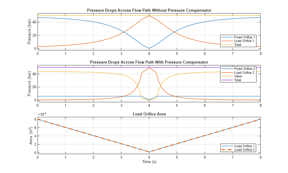
These plots show the pressure drops in the system. Because of the initial large opening of the Load Orifice 1, the pressure drop across the Fixed Orifice 1 begins at a value close to the total pressure drop of 50 bar, which the pressure source specifies. The pressure drop reduces to zero when the Load Orifice 1 fully closes. In contrast, the pressure drop across the Fixed Orifice 2 is equal to or less than the maximum regulation pressure 6.075 bar, which is the sum of the set pressure differential 6 bar and the pressure regulation range 0.075 bar. The flow rate along the Fixed Orifice 2 remains nearly constant when the valve partially opens, because the pressure drop across the orifice lies in a small range between 6 bar and 6.075 bar. When the pressure drop across the Load Orifice 2 increases due to the decreasing orifice opening, the pressure drop across the Fixed Orifice 2 begins to fall below the set pressure differential 6 bar. This behavior maintains the total pressure drop of 50 bar.