Sequencing Circuit for Two Rotary Actuators
Warning: This example uses the hydraulic domain, which will be removed in a future release. Find an equivalent example model that uses the isothermal liquid domain here: Sequencing Circuit for Two Rotary Actuators. To convert models to the isothermal liquid domain, use the hydraulicToIsothermalLiquid tool.
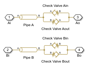
This example shows a sequence circuit that is based on four check valves installed in both pressure and return lines of the second rotary actuator. The cracking pressure of all the valves is set higher than any load pressure of Rotary Actuator 1, but lower than pressure that develops in its chambers at the end of the stroke when Rotary Actuator 1 reaches its hard stop. As a result, the Rotary Actuator 2 starts moving only after the Rotary Actuator 1 completes its stroke.
Model

Sequence Valves Subsystem
Simulation Results from Simscape Logging
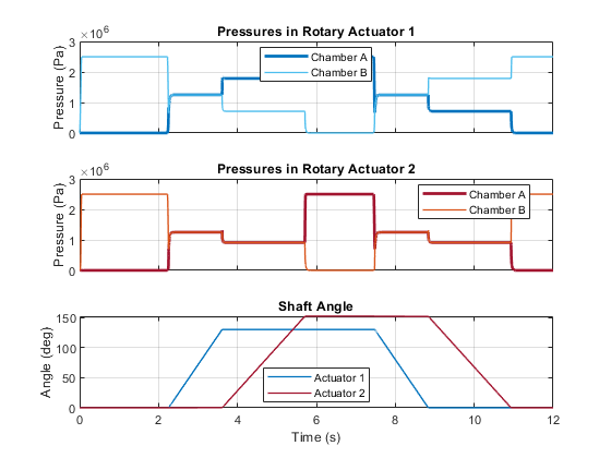
The plots below show the sequence of pressures in the rotary actuator chambers. At the start of the simulation, both actuators are driven against their hard stops at 0 degrees. At 2 seconds, the high pressure line is connected to the opposite chamber of the actuators. The sequencing valves (check valves) prevent flow to actuator 2 until actuator 1 reaches its hard stop. At that point, the pressure rises enough to overcome the check valves and actuator 2 rotates. The opposing set of check valves are similarly tuned to repeat this pattern in the opposite direction.