LTE DL-SCH and PDSCH Processing Chain
In LTE the Downlink Shared Channel (DL-SCH) is a transport channel used for the transmission of user data, dedicated control and user-specific higher layer information and downlink system information. The Physical Downlink Shared Channel (PDSCH) is the physical channel that carries the DL-SCH coded data. This example shows the different stages involved in the Downlink Shared Channel (DL-SCH) and Physical Downlink Shared Channel (PDSCH) processing and provides access to the data from these intermediate stages.
Introduction
The LTE Toolbox™ provides functions for physical layer modeling with varying levels of granularity ranging from system level functions that can generate the full uplink and downlink waveforms to PHY channel level functions that perform the transport/physical channel processing and individual channel processing stage functions performing CRC coding, turbo coding, etc. These functions, with the simple interface and ease of parameterization, help in rapid prototyping of standard compliant models and therefore are useful in a wide variety of applications. The advantages of a test and verification workflow using individual channel processing stages illustrated in this example are:
Use as golden reference for alternate implementations
Ease of creating static or dynamic test vectors for receiver or hardware unit testing
Understand the DL-SCH/PDSCH processing
The varying levels of granularity allows the users to create models with as much access to intermediate data as required and generate a large number of waveforms or test vectors for automated testing. For the DL-SCH and PDSCH processing and decoding, the toolbox provides lteDLSCH, ltePDSCH, ltePDSCHDecode and lteDLSCHDecode. These are channel level functions capable of processing all stages of the relevant transport or physical channel as described in TS 36.212 Section 5.3.2 [ 1 ] and TS 36.211 Section 6.4 [ 2 ]. This example shows how to use the functions performing individual channel processing steps for DL-SCH and PDSCH encoding and decoding for the use cases where access to the intermediate values/processing stages are required. The various stages of the processing chain and the functions the LTE Toolbox provides for the DL-SCH and PDSCH are shown by the diagrams below.
Setup
The functions used in the example require a combination of cell-wide parameters and channel specific parameters. These are input to the functions as fields of structures or as individual parameters.
% Cell-wide Settings
% The cell-wide parameters are grouped into a single structure enb. A
% number of the functions used in this example require a subset of the
% parameters specified below. In this example we use the configuration
% according to the RMC R.14 FDD specified in TS 36.101 Annex A.3.4 which
% uses 50 RB, 4 port, 'SpatialMux' transmission scheme, '16QAM' symbol
% modulation, 2 codewords and a code rate of 1/2.
enb.NDLRB = 50;                 % Number of resource blocks
enb.CellRefP = 4;               % Cell-specific reference signal ports
enb.NCellID = 0;                % Cell ID
enb.CyclicPrefix = 'Normal';    % Normal cyclic prefix
enb.CFI = 2;                    % Length of control region
enb.DuplexMode = 'FDD';         % FDD duplex mode
enb.TDDConfig = 1;              % Uplink/Downlink configuration (TDD only)
enb.SSC = 4;                    % Special subframe configuration (TDD only)
enb.NSubframe = 0;              % Subframe number

% Transport/Physical channel settings for ease of use the DL-SCH and PDSCH
% channel specific settings are specified in a parameter structure pdsch.
% For the R.14 FDD RMC, there are two codewords, so the modulation scheme
% is specified as a cell array containing the modulation schemes of both
% codewords. If configuring for one codeword, the modulation scheme can be
% a character vector or a cell array with character vectors.
% It is also important to configure the TrBlkSizes parameter to have the
% correct number of elements as the intended number of codewords. The
% number of soft bits for the rate matching stage is decided by the UE
% category as specified in TS 36.306 Table 4.1-1. In this example, the
% transport block size is looked up from tables in TS 36.101 Annex A.3.4.
% This can also be done by using the lteRMCDL function for R.14 RMC.

% DL-SCH Settings
TrBlkSizes = [11448; 11448];    % 2 elements for 2 codeword transmission
pdsch.RV = [0 0];               % RV for the 2 codewords
pdsch.NSoftbits = 1237248;      % No of soft channel bits for UE category 2
% PDSCH Settings
pdsch.TxScheme = 'SpatialMux';  % Transmission scheme used
pdsch.Modulation = {'16QAM','16QAM'}; % Symbol modulation for 2 codewords
pdsch.NLayers = 2;              % Two spatial transmission layers
pdsch.NTxAnts = 2;              % Number of transmit antennas
pdsch.RNTI = 1;                 % The RNTI value
pdsch.PRBSet = (0:enb.NDLRB-1)';% The PRBs for full allocation
pdsch.PMISet = 0;               % Precoding matrix index
pdsch.W = 1;                    % No UE-specific beamforming
% Only required for 'Port5', 'Port7-8', 'Port8' and 'Port7-14' schemes
if any(strcmpi(pdsch.TxScheme,{'Port5','Port7-8','Port8', 'Port7-14'}))
    pdsch.W = transpose(lteCSICodebook(pdsch.NLayers,pdsch.NTxAnts,[0 0]));
end
Downlink Shared Channel (DL-SCH) Processing
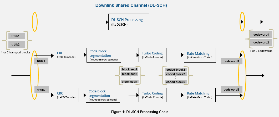
This section explains the DL-SCH transport channel coding. One transport block enters the processing chain every scheduled subframe (for spatial multiplexing schemes, there can be two transport blocks). The transport blocks get coded and rate matched to the PDSCH channel bit capacity. The PDSCH capacity depends on the PRB allocations, modulation scheme, and transmission scheme and this value is provided as an output from the ltePDSCHIndices function. The transport channel encoding process includes the following stages as shown in figure 1 above.
Transport Block CRC attachment: Error detection for the transport blocks are provided by a 24-bit CRC according to TS 36.212 Section 5.3.2.1 [ 1 ].
Code block segmentation and code block CRC attachment: As shown in the figure 1 above, code block segmentation splits the input data bit vector into a cell array of code block segments (with filler bits and type-24B CRC appended as appropriate) according to the rules of TS 36.212 Section 5.3.2.2 [ 1 ]. The function
lteDLSCHInfoprovides code block segmentation information for the given block size.Channel Coding: The code blocks are individually turbo coded according to TS 36.212 Section 5.3.2.3 [ 1 ]. The turbo coder (
lteTurboEncode) can process a cell array containing all code block segments in parallel and returns a cell array containing the individual turbo coded block segments.Rate Matching and code block concatenation: The turbo coded blocks are then individually rate matched according to TS 36.212 Section 5.3.2.4 [ 1 ] and the resulting rate matched blocks are concatenated as per TS 36.212 Section 5.3.2.5 [ 1 ] to create a single codeword for transmission on the PDSCH.
% Random number initialization for creating random transport block(s)
rng('default');

% Convert the modulation scheme char array or cell array to string array
% for uniform processing
 pdsch.Modulation = string(pdsch.Modulation);

% Get the number of codewords from the number of transport blocks
nCodewords = numel(TrBlkSizes);

% Generate the transport block(s)
trBlk = cell(1,nCodewords); % Initialize the codeword(s)
for n=1:nCodewords
    trBlk{n} = randi([0 1],TrBlkSizes(n),1);
end
% Get the physical channel bit capacity required for rate matching from
% ltePDSCHIndices info output
[~,pdschInfo] = ltePDSCHIndices(enb,pdsch,pdsch.PRBSet);

% Define a structure array with parameters for lteRateMatchTurbo
chs = pdsch;
chs(nCodewords) = pdsch; % For 2 codewords, the array has two elements
% Initialize the codeword(s)
cw = cell(1,nCodewords);
for n=1:nCodewords
    % CRC addition for the transport block
    crccoded = lteCRCEncode(trBlk{n},'24A');
    % Code block segmentation returns a cell array of code block segments
    % with filler bits and type-24B CRC appended as required
    blksegmented = lteCodeBlockSegment(crccoded);
    % Channel coding returns the turbo coded segments in a cell array
    chencoded = lteTurboEncode(blksegmented);

    % Bundle the parameters in structure chs for rate matching as the
    % function requires both cell-wide and channel specific parameters
    chs(n).Modulation = pdsch.Modulation{n};
    chs(n).DuplexMode = enb.DuplexMode;
    chs(n).TDDConfig = enb.TDDConfig;
    % Calculate number of layers for the codeword
    if n==1
        chs(n).NLayers = floor(pdsch.NLayers/nCodewords);
    else
        chs(n).NLayers = ceil(pdsch.NLayers/nCodewords);
    end
    % Rate matching returns a codeword after sub-block interleaving, bit
    % collection and bit selection and pruning defined for turbo encoded
    % data and merging the cell array of code block segments
    cw{n} = lteRateMatchTurbo(chencoded,pdschInfo.G(n),pdsch.RV(n),chs(n));
end
Physical Downlink Shared Channel (PDSCH) Processing
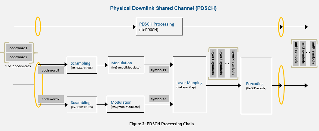
One or two transport coded blocks (codewords) can be transmitted simultaneously on the PDSCH depending on the transmission scheme used (see TS 36.211 section 6.4 [ 2 ]). As shown in figure 2 above, the codewords undergo scrambling, modulation, layer mapping, precoding, optional UE-specific beamforming, and resource element mapping. The size of the matrix precoded is N-by-P with N being the number of modulation symbols for one antenna port, and P being the number of transmission antennas.
Scrambling: Up to two codewords can be transmitted in a subframe and for each codeword, the bits are scrambled with a different scrambling sequence according to TS 36.211 Section 6.3.1 [ 2 ]. The scrambling sequence is initialized at the start of each subframe and depends on
RNTI,NCellID,NSubframeand the codeword index.Modulation: The scrambled codeword(s) is then symbol modulated using one of the modulation schemes ('QPSK', '16QAM', '64QAM' or '256QAM').
Layer Mapping: The complex modulated symbols are then mapped on to one or several layers according to the transmission scheme used (TS 36.211 Section 6.3.3 [ 1 ]). For single port (port 0, 5, 7 or 8), a single layer is used. For transmit diversity only one codeword is allowed and the number of layers (2 or 4) must be equal to the number of antenna ports used for the transmission of the physical channel. For spatial multiplexing 1 or 2 codewords can be transmitted on up to 8 layers. The number of layers is less than or equal to the number of antenna ports used for transmission of the physical channel.
Precoding: The precoding stage takes in the M-by-Layers matrix from the layer mapping stage and returns the matrix of size M-by-P for transmission on P antennas as defined in TS 36.211 Section 6.3.4 [ 2 ]. For single port (port 0, 5, 7 or 8), this stage is transparent and for transmit diversity, precoding is applied for 2 or 4 antenna ports. Precoding for spatial multiplexing depends on whether antenna ports with cell-specific reference signals ('SpatialMux', 'CDD' and 'MultiUser' transmission schemes) or antenna ports with UE-specific reference signals ('Port5', 'Port7-8', 'Port8' and 'Port7-14' transmission schemes) are used.
Mapping to Resource Elements: The complex modulated symbols are then mapped on to the resource elements as defined in TS 36.211 Section 6.3.5 [ 2 ] to create the grid for transmission. This stage is not shown in this example, but can be easily done by creating an empty resource grid using
lteDLResourceGridand mapping the symbols to resource elements returned by theltePDSCHIndicesfunction.
% Initialize the modulated symbols
modulated = cell(1,nCodewords);
for n=1:nCodewords
   % Generate the scrambling sequence
   scramseq = ltePDSCHPRBS(enb,pdsch.RNTI,n-1,length(cw{n}));
   % Scramble the codewords
   scrambled = xor(scramseq,cw{n});
   % Symbol modulate the scrambled codewords
   modulated{n} = lteSymbolModulate(scrambled,pdsch.Modulation{n});
end
% Layer mapping results in a (symbols per layer)-by-NLayers matrix
layermapped = lteLayerMap(pdsch,modulated);
% Precoding results in a (symbols per antenna)-by-NTxAnts matrix
precoded = lteDLPrecode(enb, pdsch, layermapped);
% Apply beamforming optionally (W should be 1 or identity if no beamforming)
pdschsymbols = precoded*pdsch.W;
PDSCH Decoding
The decoding is the inverse of Physical Downlink Shared Channel (PDSCH) processing on the matrix of complex modulated PDSCH symbols, depending on cell-wide settings structure enb and channel-specific configuration structure pdsch. The channel inverse processing includes the deprecoding, layer demapping and codeword separation, soft demodulation, and descrambling. The deprecoding is performed using matrix pseudo inversion of the precoding matrices. For applications involving propagation channels and/or noise, channel estimation and equalization is done on the received symbols before decoding. See ltePDSCHDecode for further information.
% Deprecoding (pseudo-inverse based) returns (Number of symbols)-by-NLayers matrix
if (any(strcmpi(pdsch.TxScheme,{'Port5' 'Port7-8' 'Port8' 'Port7-14'})))
    rxdeprecoded=pdschsymbols*pinv(pdsch.W);
else
    rxdeprecoded = lteDLDeprecode(enb,pdsch,pdschsymbols);
end
% Layer demapping returns a cell array containing one or two codewords. The
% number of codewords is deduced from the number of modulation scheme
% character vectors
layerdemapped = lteLayerDemap(pdsch,rxdeprecoded);

% Initialize the recovered codewords
cws = cell(1,nCodewords);
for n=1:nCodewords
    % Soft demodulation of received symbols
    demodulated = lteSymbolDemodulate(layerdemapped{n},pdsch.Modulation{n},'Soft');
    % Scrambling sequence generation for descrambling
    scramseq = ltePDSCHPRBS(enb,pdsch.RNTI,n-1,length(demodulated),'signed');
    % Descrambling of received bits
    cws{n} = demodulated.*scramseq;
end
DL-SCH Decoding
The Downlink Shared Channel (DL-SCH) decoding includes rate recovery, turbo decoding, block concatenation and CRC calculations. Alternatively the function lteDLSCHDecode also provides the same functionality. This function also returns the type-24A transport block CRC decoding result, type-24B code block set CRC decoding result, the HARQ process decoding state, and provides parameterization for specifying the initial HARQ process state.
% Initialize the received transport block and CRC
rxTrBlk = cell(1,nCodewords);
crcError = zeros(1,nCodewords);
for n=1:nCodewords
    % Rate recovery stage also allows combining with soft information for
    % the HARQ process, using the input cbsbuffers. For the first
    % transmission of the transport block, the soft buffers are initialized
    % as empty. For retransmissions, the parameter cbsbuffers should be the
    % soft information from the previous transmission
    cbsbuffers = [];  % Initial transmission of the HARQ process
    % Rate recovery returns a cell array of turbo encoded code blocks
    raterecovered = lteRateRecoverTurbo(cws{n},TrBlkSizes,pdsch.RV(n),chs(n),cbsbuffers);
    NTurboDecIts = 5; % Number of turbo decoding iteration cycles
    % Turbo decoding returns a cell array of decoded code blocks
    turbodecoded = lteTurboDecode(raterecovered,NTurboDecIts);
    % Code block desegmentation concatenates the input code block segments
    % into a single output data block, after removing any filler and
    % type-24B CRC bits that may be present
    [blkdesegmented,segErr] = lteCodeBlockDesegment(turbodecoded,(TrBlkSizes+24));
    % CRC decoding returns the transport block after checking for CRC error
    [rxTrBlk{n},crcError(n)] = lteCRCDecode(blkdesegmented,'24A');
end
Conclusion
This example explained the Downlink Shared Channel (DL-SCH) and Physical Downlink Shared Channel (PDSCH) processing and provided an insight into the different functions available within LTE Toolbox to support these channels. The example also illustrated how the low level functions can be used to model the channels and this approach can be used in applications including golden reference test vector generation from these intermediate processing stages to independently validate the different processing stages of alternate implementations. This example also shows how the LTE Toolbox and MATLAB® platform enables the creation of a powerful environment for large scale verification and test.
Further Exploration
You can modify the parameters provided in this example to experiment with different configurations. For e.g. when simulating for different transmission modes, some of the parameters of interest are transmission scheme (TxScheme), modulation scheme (Modulation), number of codewords (number of elements of TrBlkSizes).
Selected Bibliography
3GPP TS 36.212 "Multiplexing and channel coding"
3GPP TS 36.211 "Physical channels and modulation"
3GPP TS 36.213 "Physical layer procedures"
3GPP TS 36.101 "User Equipment (UE) radio transmission and reception"
3GPP TS 36.306 "User Equipment (UE) radio access capabilities"