Run-Time Parameter Estimation of PMSM Using Sensor Feedback
This example shows how to estimate the parameters of a permanent magnet synchronous motor (PMSM) at run-time. The example estimates the following PMSM parameters by running tests while the motor runs using a closed-loop field-oriented control (FOC) algorithm:
Permanent magnet flux linkage, FluxPM (Wb)
Stator d-axis inductance, Ld (H)
Stator resistance, Rs (ohm)
Motor parameter estimation is vital for implementing motor control algorithms accurately. Accurate motor parameters enable the algorithms to compute the control parameters with precision. Therefore, an accurate representation of motor parameters is necessary for a finer speed and torque control when you run PMSMs using control techniques such as field-oriented control (FOC). Motor parameter estimation also enables you to verify the parameter values provided by the motor datasheet. In addition, it enables you to accurately replicate the plant model in Simulink® using which you can simulate real-world scenarios and tests that are difficult to execute using a physical hardware setup.
An accurate simulation helps you reconfigure and run these tests multiple times, which can be difficult when you use physical hardware. Therefore, these exhaustive tests enable you to predict, find, and fix problems with ease including failures that are hard-to-reproduce.
This example uses a unique approach of running parameter estimation tests while the motor is actually running using FOC. The following sections explain about the parameter estimation algorithms that the example uses to estimate FluxPM and Ld parameters.
Extended Kalman Filter for Estimating Rotor Flux
The example uses an Extended Kalman Filter (EKF) to estimate the permanent magnet flux linkage (FluxPM) parameter of a PMSM in webers.
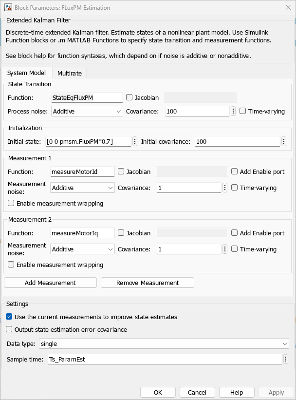
You can use EKF-based algorithms for effective online state estimation of discrete-time non-linear systems such as a PMSM. The example uses the Extended Kalman Filter (System Identification Toolbox) block to implement such an algorithm that utilizes state transition and measurement functions of the motor control system along with EKF to estimate the FluxPM parameter for the current time step.
The following figures show the Extended Kalman Filter block with the name FluxPM Estimation (available in the PMSMRuntimeParameterEstimationF28379d/ParamEstimation subsystem) that defines the nonlinear state transition function and measurement functions for the FOC-based motor control system.

The following state transition equations describe the mathematical computation performed by the EKF-based algorithm that the example uses to estimate FluxPM.

where:
 and
and  are the stator d-axis and q-axis currents (in amperes).
 and
and  are the stator d-axis and q-axis voltages (in volts).
 and
and  are the stator d-axis and q-axis inductances (in henries).
R is the stator resistance (in ohms).
P is the number of pole pairs of the PMSM.
 is the mechanical speed of the PMSM (in RPM).
 is the permanent magnet flux linkage, Flux PM (in webers).
The MotorStateEqFlux MATLAB® function available in the PMSMRuntimeParameterEstimationF28379d/ParamEstimation/StateEqFluxPM subsystem implements the preceding state transition equations as shown in the following figures.


For more information about the EKF-based algorithm used by this example, see Extended and Unscented Kalman Filter Algorithms for Online State Estimation (System Identification Toolbox).
Recursive Least Square Algorithm for Estimating Stator Inductance
The example uses a recursive least squares (RLS) algorithm to estimate the stator d-axis inductance (Ld) parameter of a PMSM in henries.
You can use an RLS-based algorithm for online parameter estimation of dynamic systems, such as electric motors. You can use this algorithm to estimate system parameters in real-time as the new data becomes available. The example uses the Recursive Least Squares Estimator (System Identification Toolbox) block to implement RLS-based recursive estimation algorithm that utilizes linear regression form of motor equations to estimate the Ld parameter for the current time step.
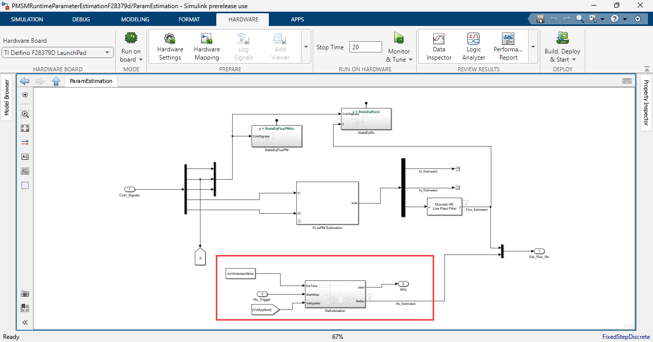
The following figure shows the RLS-based algorithm (utilizing the Recursive Least Squares Estimator block) available in the PMSMRuntimeParameterEstimationF28379d/ParamEstimation subsystem.

Use the Recursive Least Squares Estimator block parameters dialog box to configure the model parameters as well as the RLS algorithm options. For more details, see Recursive Least Squares Estimator (System Identification Toolbox).

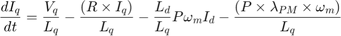
The following equations describe the mathematical computation performed by the RLS-based algorithm that the example uses to estimate Ld.
where:
- and are the stator d-axis and q-axis currents (in amperes).
- is the stator d-axis voltage (in volts).
- and are the stator d-axis and q-axis inductances (in henries).
R is the stator resistance (in ohms).
P is the number of pole pairs of the PMSM.
- is the mechanical speed of the PMSM (in RPM).
- is the permanent magnet flux linkage, Flux PM (in webers).
For more information about the RLS-based algorithm used by this example, see Recursive Algorithms for Online Parameter Estimation (System Identification Toolbox).
Note:
Both EKF and RLS algorithms that the example uses are sensitive to changes in stator resistance value (R).
The RLS algorithm uses a sample time (Ts) that is identical to that of the current controller. Whereas, the EKF algorithm uses a higher sample time of (10 x Ts).
The example uses quadrature encoder sensor for measuring the rotor position.
Estimate Stator Resistance (Rs)
The example uses Rs estimation (RSE) algorithm by injecting a current signal in the d-axis of stator current. While injecting for a short time, the q-axis current is kept constant.
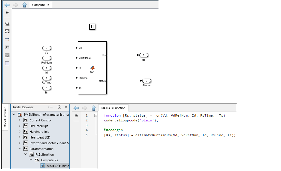
The following figure shows the RSE algorithm available in the PMSMRuntimeParameterEstimationF28379d/ParamEstimation subsystem.
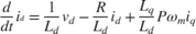
The following equation describes the mathematical computation performed by the RSE algorithm that the example uses to estimate Rs.
where:
- and are the stator d-axis and q-axis currents (in amperes).
- is the stator d-axis voltage (in volts).
- and are the stator d-axis and q-axis inductances (in henries).
R is the stator resistance (in ohms).
P is the number of pole pairs of the PMSM.
- is the mechanical speed of the PMSM (in RPM).
The algorithm finds the difference in voltage based to the injected current and uses this formula to estimate Rs:

The MATLAB Function in the subsystem estimates Rs based on the above equation.
Model
The example includes the target model PMSMRuntimeParameterEstimationF28379d.

You can use this model for both simulation and code generation.
For details about the supported hardware configuration, see the Required Hardware topic in the Generate Code and Deploy Model to Target Hardware section.
Required MathWorks Products
To simulate model:
Motor Control Blockset™
System Identification Toolbox™
To generate code and deploy model:
Motor Control Blockset
System Identification Toolbox
Embedded Coder®
C2000™ Microcontroller Blockset
Fixed-Point Designer™ (only needed when you use fixed-point data type for optimized code generation)
Prerequisites
Check and update the mandatory motor, inverter, and other system parameters listed in the model initialization script PMSMRuntimeParameterEstimationF28379dData.
In addition, you can update the optional motor parameters for simulation.
You can use the inverter and motor hardware datasheet to determine these values.
Simulate Model
This example supports simulation. Complete these steps to simulate the model.
1. Open the target model included in this example.
2. Use the Select Parameter section to select one of the following parameters that you want to estimate:
Flux Estimation — Select this radio button to configure the target model to estimate the permanent magnet flux linkage (FluxPM) in webers.
Inductance Estimation — Select this radio button to configure the target model to estimate the stator d-axis inductance (Ld) in henries.
3. Click Run on the Simulation tab to simulate the model.
4. Observe the estimated value of the selected parameter in the Parameter Estimation section of the target model.
Generate Code and Deploy Model to Target Hardware
This section shows you how to generate code and run the run-time parameter estimation algorithm on the target hardware to estimate the parameters of the connected motor.
This example uses a host and a target model. The host model is a user interface to the controller hardware board. You can run the host model on the host computer. To use the host model, first deploy the target model to the controller hardware board. The host model uses serial communication to command the target to run the run-time parameter estimation tests.
Required Hardware
The example supports this hardware configuration. You can also use the target model name to open the model from the MATLAB command prompt.
LAUNCHXL-F28379D controller + BOOSTXL-DRV8305 inverter:
PMSMRuntimeParameterEstimationF28379d
For connections related to the hardware configuration, see LAUNCHXL-F28069M and LAUNCHXL-F28379D Configurations.
Generate Code and Run Model on Target Hardware
1. Complete the hardware connections.
2. The model automatically computes the ADC (or current) offset values. To disable this functionality (enabled by default), update the value 0 to the variable inverter.ADCOffsetCalibEnable in the model initialization script PMSMRuntimeParameterEstimationF28379dData.
Alternatively, you can compute the ADC offset values and update them manually in the model initialization script. For instructions, see Run 3-Phase AC Motors in Open-Loop Control and Calibrate ADC Offset.
3. Compute the quadrature encoder index offset value and update it in the model initialization script PMSMRuntimeParameterEstimationF28379dData. For instructions, see Quadrature Encoder Offset Calibration for PMSM.
Note: Verify the number of slits available in the quadrature encoder sensor attached to your motor. Check and update the variable pmsm.QEPSlits available in the model initialization script. This variable corresponds to the Encoder slits parameter of the quadrature encoder block. For more details about the Encoder slits and Encoder counts per slit parameters, see Quadrature Decoder.
4. Open the target model. If you want to change the default hardware configuration settings for the model, see Model Configuration Parameters.
5. Load a sample program to CPU2 of the LAUNCHXL-F28379D board to ensure that CPU2 is not mistakenly configured to use the board peripherals intended for CPU1. For example, load the program that operates the CPU2 blue LED by using GPIO31 (c28379D_cpu2_blink.slx). For more information about the sample program or model, see the Task 2 - Create, Configure and Run the Model for TI Delfino F28379D LaunchPad (Dual Core) section in Getting Started with Texas Instruments C2000 Microcontroller Blockset (C2000 Microcontroller Blockset).
6. Click Build, Deploy & Start on the Hardware tab to deploy the target model to the hardware.
7. Verify that the variables from the target model are available in the MATLAB base workspace.
8. Click the PMSMRuntimeParameterEstimationF28379dHost.slx host model hyperlink in the target model to open the associated host model.

For details about serial communication between the host and target models, see Host-Target Communication.
9. In the model initialization script PMSMRuntimeParameterEstimationF28379dData associated with the target model, specify the communication port using the variable target.comport. This variable updates the Port parameter of the Host Serial Setup, Host Serial Receive, and Host Serial Transmit blocks available in the host model.
10. Use the Reference Speed (RPM) field in the host model to set a reference speed that deployed target model should use to run the motor.
11. Set the Select Parameter Estimation switch to one of the following values:
Permanent magnet flux — Select this value to configure the target model to estimate the permanent magnet flux linkage (FluxPM) in webers.
Stator d-axis inductance — Select this value to configure the target model to estimate the stator d-axis inductance (Ld) in webers.
12. Click Run on the Simulation tab to run the host model. This initiates communication between the host model and target hardware.
13. Use the Motor switch to start running the motor and begin the parameter estimation tests (for the selected parameter).
14. Use the Debug Signals combo box to select a debug signal. Monitor the selected signal in the Scope and Display blocks available in the host model.
See Also
Apps
Blocks
- Extended Kalman Filter (System Identification Toolbox) | Recursive Least Squares Estimator (System Identification Toolbox) | PMSM Rs Estimator | Ld Estimator | Lq Estimator | PMSM Mechanical Parameter Estimator | PMSM Parameter Estimation Configurator | ACIM Parameter Estimation Configurator | Id0 Estimator | ACIM Rs Estimator | RrL Estimator | ACIM Mechanical Parameter Estimator
Topics
- Estimate PMSM Parameters Using Custom Hardware
- Estimate Induction Motor Parameters Using Parameter Estimation Blocks
- Estimate PMSM Parameters Using Parameter Estimation Blocks
- Estimate PMSM Parameters Using Parameter Estimation Blocks on Real-Time Systems
- Estimate PMSM Parameters Using FPGA-Based Motor Control Development Kit
- Generate Motor Control Models for Selected Algorithm and Hardware
- Extended and Unscented Kalman Filter Algorithms for Online State Estimation (System Identification Toolbox)
- Recursive Algorithms for Online Parameter Estimation (System Identification Toolbox)