Automate Testing for Highway Lane Following
This example shows how to assess the functionality of a lane-following application by defining scenarios based on requirements, automating testing of components and the generated code for those components. The components include lane-detection, sensor fusion, decision logic, and controls. This example builds on the Highway Lane Following (Automated Driving Toolbox) example.
Introduction
A highway lane-following system steers a vehicle to travel within a marked lane. It also maintains a set velocity or safe distance from a preceding vehicle in the same lane. The system typically includes lane detection, sensor fusion, decision logic, and controls components. System-level simulation is a common technique for assessing functionality of the integrated components. Simulations are configured to test scenarios based on system requirements. Automatically running these simulations enables regression testing to verify system-level functionality.
The Highway Lane Following (Automated Driving Toolbox) example showed how to simulate a system-level model for lane-following. This example shows how to automate testing that model against multiple scenarios using Simulink Test™. The scenarios are based on system-level requirements. In this example, you will:
Review requirements: The requirements describe system-level test conditions. Simulation test scenarios are created to represent these conditions.
Review the test bench model: Review the system-level lane-following test bench model that contains metric assessments. These metric assessments integrate the test bench model with Simulink Test for the automated testing.
Disable runtime visualizations: Runtime visualizations are disabled to reduce execution time for the automated testing.
Automate testing: A test manager is configured to simulate each test scenario, assess success criteria, and report results. The results are explored dynamically in the test manager and exported to a PDF for external reviewers.
Automate testing with generated code: The lane detection, sensor fusion, decision logic, and controls components are configured to generate C++ code. The automated testing is run on the generated code to verify expected behavior.
Automate testing in parallel: Overall execution time for running the tests is reduced using parallel computing on a multi-core computer.
Testing the system-level model requires a photorealistic simulation environment. In this example, you enable system-level simulation through integration with the Unreal Engine from Epic Games®. This example requires a Windows® 64-bit platform.
if ~ispc
    error(['This example is supported only on Microsoft', char(174),' Windows 64-bit platform.'])
end
To ensure reproducibility of the simulation results, set the random seed.
rng(0);
Review Requirements
Requirements Toolbox™ lets you author, analyze, and manage requirements within Simulink. This example contains ten test scenarios, with high-level testing requirements defined for each scenario. Open the requirement set.
To explore the test bench model, load the highway lane following project.
openProject("HighwayLaneFollowing");
open('HighwayLaneFollowingTestRequirements.slreqx')
Alternatively, you can also open the file from the Requirements tab of the Requirements Manager app in Simulink.
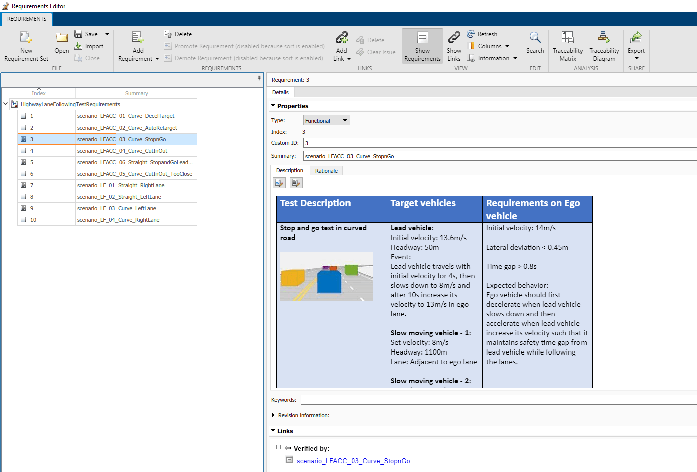
Each row in this file specifies the requirements in textual and graphical formats for testing the lane-following system for a test scenario. The scenarios with the scenario_LF_ prefix enable you to test lane-detection and lane-following algorithms without obstruction by other vehicles. The scenarios with the scenario_LFACC_ prefix enable you to test lane-detection, lane-following, and ACC behavior with other vehicles on the road.
scenario_LF_01_Straight_RightLane— Straight road scenario with ego vehicle in right lane.scenario_LF_02_Straight_LeftLane— Straight road scenario with ego vehicle in left lane.scenario_LF_03_Curve_LeftLane— Curved road scenario with ego vehicle in left lane.scenario_LF_04_Curve_RightLane— Curved road scenario with ego vehicle in right lane.scenario_LFACC_01_Curve_DecelTarget— Curved road scenario with a decelerating lead vehicle in ego lane.scenario_LFACC_02_Curve_AutoRetarget— Curved road scenario with changing lead vehicles in ego lane. This scenario tests the ability of the ego vehicle to retarget to a new lead vehicle while driving along a curve.scenario_LFACC_03_Curve_StopnGo— Curved road scenario with a lead vehicle slowing down in ego lane.scenario_LFACC_04_Curve_CutInOut— Curved road scenario with a fast moving car in the adjacent lane cuts into the ego lane and cuts out from ego lane.scenario_LFACC_05_Curve_CutInOut_TooClose— Curved road scenario with a fast moving car in the adjacent lane cuts into the ego lane and cuts out from ego lane aggressively.scenario_LFACC_06_Straight_StopandGoLeadCar— Straight road scenario with a lead vehicle that breaks down in ego lane.
These requirements are implemented as test scenarios with the same names as the scenarios used in the HighwayLaneFollowingTestBench model.
Review Test Bench Model
This example reuses the HighwayLaneFollowingTestBench model from the Highway Lane Following (Automated Driving Toolbox) example. Open the test bench model.
open_system("HighwayLaneFollowingTestBench");
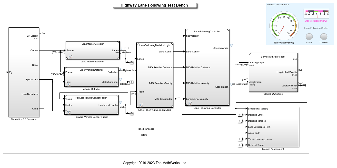
This test bench model has Simulation 3D Scenario, Lane Marker Detector, Vehicle Detector, Forward Vehicle Sensor Fusion, Lane Following Decision Logic and Lane Following Controller and Vehicle Dynamics components.
This test bench model is configured using the helperSLHighwayLaneFollowingSetup script. This setup script takes scenarioName as input. scenarioName can be any one of the previously described test scenarios. To run the setup script, use code:
scenarioName = "scenario_LFACC_03_Curve_StopnGo";
helperSLHighwayLaneFollowingSetup("scenarioFcnName",scenarioName);
You can now simulate the model and visualize the results. For more details on the analysis of the simulation results and the design of individual components in the test bench model, see the Highway Lane Following (Automated Driving Toolbox) example.
In this example, the focus is more on automating the simulation runs for this test bench model using Simulink Test for the different test scenarios. The Metrics Assessment subsystem enables integration of system-level metric evaluations with Simulink Test. Open the Metrics Assessment subsystem.
open_system("HighwayLaneFollowingTestBench/Metrics Assessment");
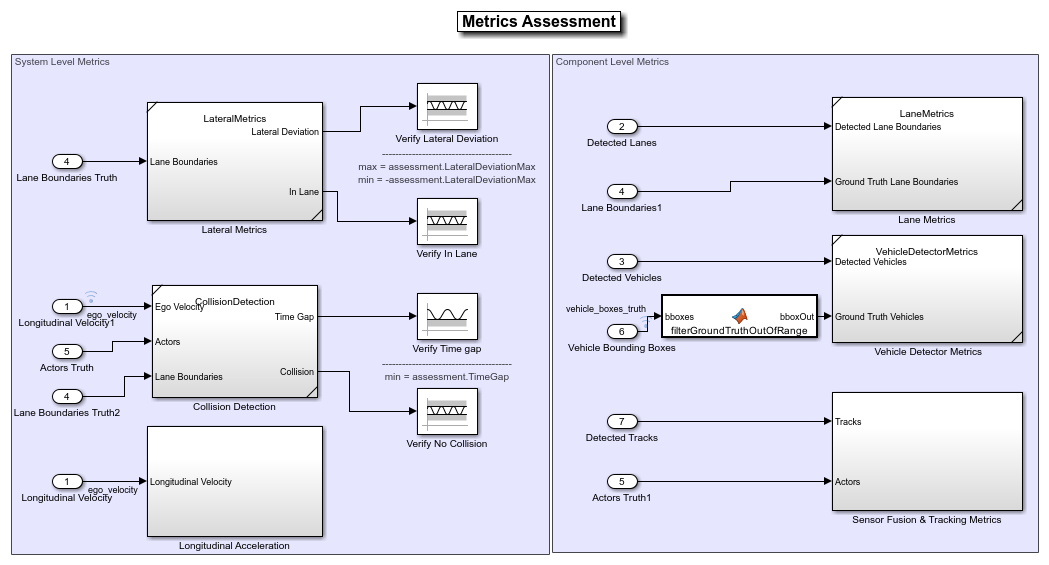
Using this example, you can evaluate the system-level behavior using four system-level metrics. Additionally, you can also compute component-level metrics to analyze individual components and their impact on the overall system performance.
System-Level Metrics
Verify Lateral Deviation — This block verifies that the lateral deviation from the center line of the lane is within prescribed thresholds for the corresponding scenario. Define the thresholds when you author the test scenario.
Verify In Lane — This block verifies that the ego vehicle is following one of the lanes on the road throughout the simulation.
Verify Time gap — This block verifies that the time gap between the ego vehicle and the lead vehicle is more than 0.8 seconds. The time gap between the two vehicles is defined as the ratio of the calculated headway distance to the ego vehicle velocity.
Verify No Collision — This block verifies that the ego vehicle does not collide with the lead vehicle at any point during the simulation.
Component-Level Metrics
Lane Metrics — This block verifies that distances between the detected lane boundaries and the ground truth data are within the thresholds specified in a test scenario.
Vehicle Detector Metrics — This blocks computes and logs true positives, false negatives, and false positives for the detections.
Sensor Fusion & Tracking Metrics — This subsystem computes generalized optimal subpattern assignment (GOSPA) metric, localization error, missed target error, and false track error. For more information on these metrics, see Forward Vehicle Sensor Fusion (Automated Driving Toolbox) example.
Disable Runtime Visualizations
The system-level test bench model visualizes intermediate outputs during the simulation for the analysis of different components in the model. These visualizations are not required when the tests are automated. You can reduce execution time for the automated testing by disabling them.
Disable runtime visualizations for the Lane Marker Detector subsystem.
load_system('LaneMarkerDetector');
blk = 'LaneMarkerDetector/Lane Marker Detector';
set_param(blk,'EnableDisplays','off');
Disable runtime visualizations for the Vehicle Detector subsystem.
load_system('VisionVehicleDetector');
blk = 'VisionVehicleDetector/Pack Detections/Pack Vehicle Detections';
set_param(blk,'EnableDisplay','off');
Configure the Simulation 3D Scene Configuration (Automated Driving Toolbox) block to run the Unreal Engine in headless mode, where the 3D simulation window is disabled.
blk = ['HighwayLaneFollowingTestBench/Simulation 3D Scenario/', ...
      'Simulation 3D Scene Configuration'];
set_param(blk,'EnableWindow','off');
Automate Testing
The Test Manager is configured to automate the testing of the lane-following application. Open the HighwayLaneFollowingTestAssessments.mldatx test file in the Test Manager.
sltestmgr;
testFile = sltest.testmanager.load('HighwayLaneFollowingTestAssessments.mldatx');
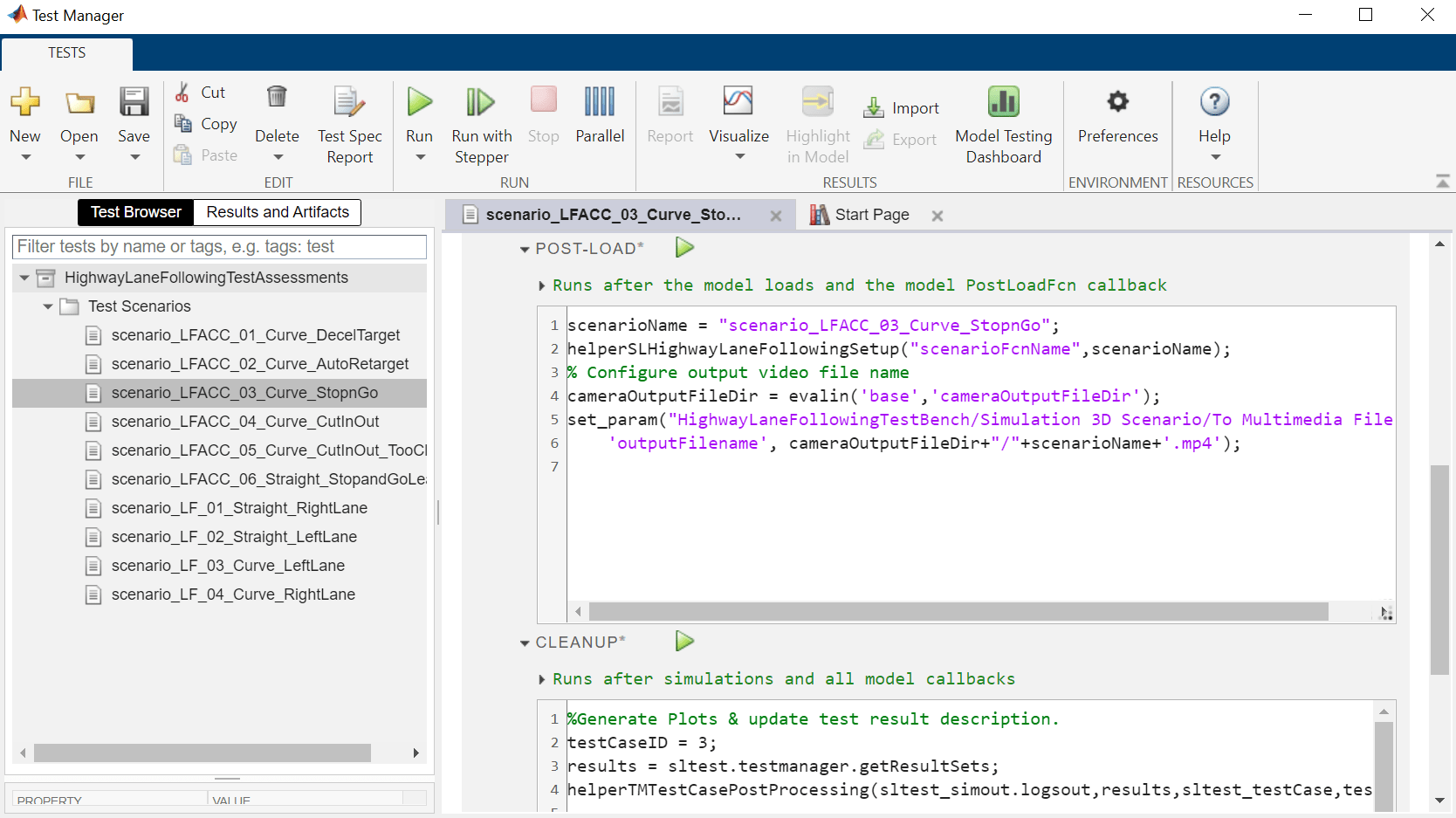
Observe the populated test cases that were authored previously in this file. Each test case is linked to the corresponding requirement in the Requirements Editor for traceability. Each test case uses the POST-LOAD callback to run the setup script with appropriate inputs and to configure the output video filename. After the simulation of the test case, it invokes helperTMTestCasePostProcessing from the CLEAN-UP callback to assess performances of the overall system and individual components by generating the plots explained in the Highway Lane Following (Automated Driving Toolbox) example.
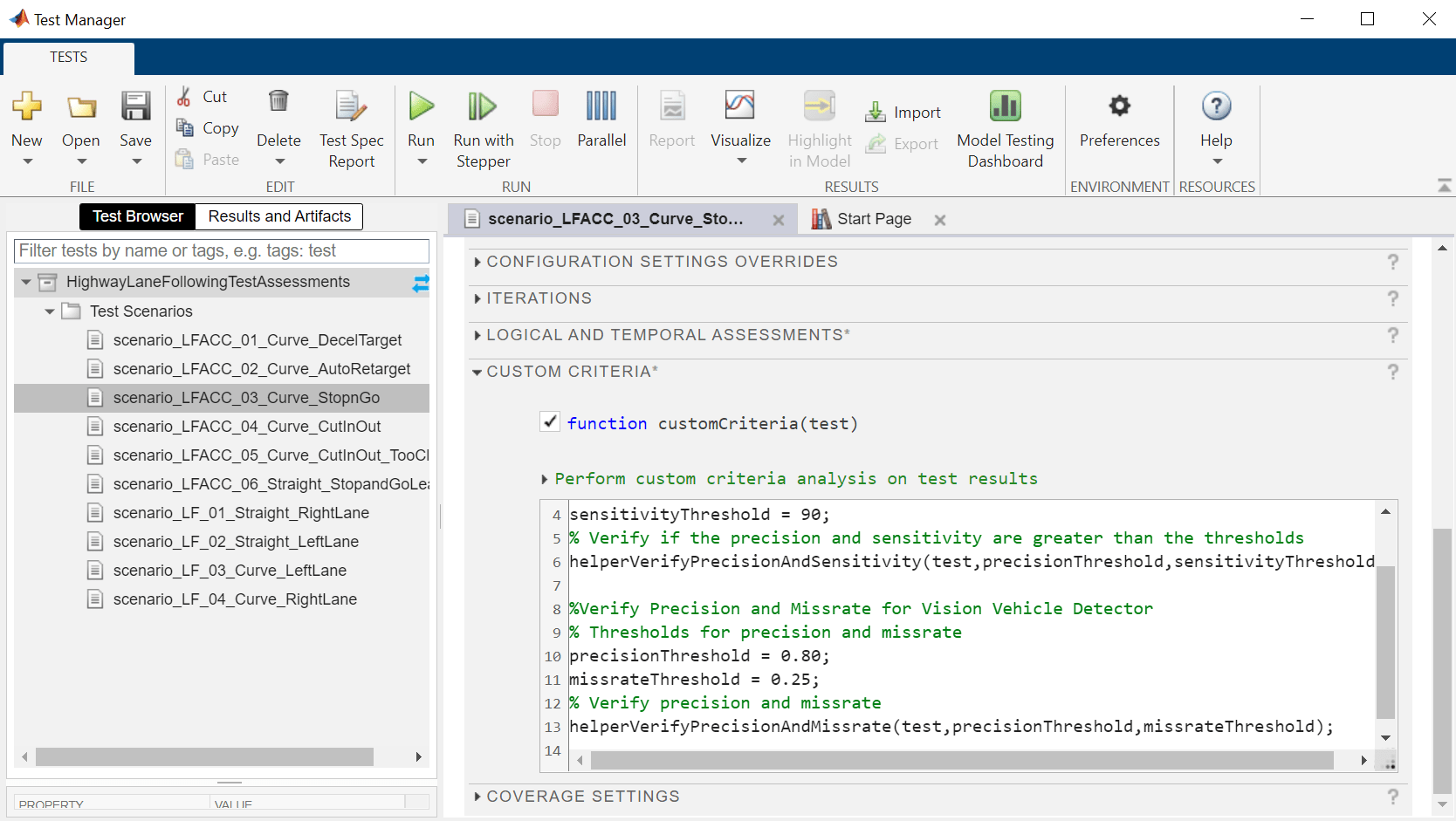
After simulation of the test case, Simulink Test also invokes these functions from the CUSTOM CRITERIA callback to get additional metrics for lane marker detector and vehicle detector components:
helperVerifyPrecisionAndSensitivity— Verifies that the precision and sensitivity metrics of the lane marker detector component are within the predefined threshold limit.helperVerifyPrecisionAndMissrate— Verifies that the precision and miss rate metrics of the vehicle detector component are within the predefined threshold limit.
Run and explore results for a single test scenario:
To reduce command-window output, turn off the MPC update messages.
mpcverbosity('off');
To test the system-level model with the scenario_LFACC_03_Curve_StopnGo test scenario from Simulink Test, use this code:
testSuite = getTestSuiteByName(testFile,'Test Scenarios');
testCase = getTestCaseByName(testSuite,'scenario_LFACC_03_Curve_StopnGo');
resultObj = run(testCase);
To generate a report after the simulation, use this code:
sltest.testmanager.report(resultObj,'Report.pdf',...,
    'Title','Highway Lane Following',...
    'IncludeMATLABFigures',true,...
    'IncludeErrorMessages',true,...
    'IncludeTestResults',0,'LaunchReport',true);
Examine the report Report.pdf. Observe that the Test environment section shows the platform on which the test is run and the MATLAB® version used for testing. The Summary section shows the outcome of the test and duration of the simulation in seconds. The Results section shows pass/fail results based on the assessment criteria. This section also shows the plots logged from the helperGenerateFilesForLaneFollowingReport function.
Run and explore results for all test scenarios:
You can simulate the system for all the tests by using sltest.testmanager.run. Alternatively, you can simulate the system by clicking Play in the Test Manager app.
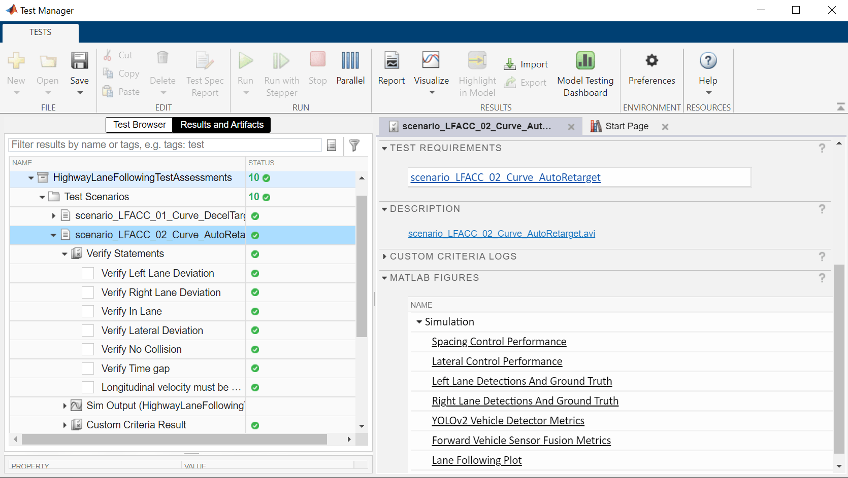
After completion of the test simulations, the results for all the tests can be viewed in the Results and Artifacts tab of the Test Manager. For each test case, the Check Static Range (Simulink) blocks in the model are associated with the Test Manager to visualize overall pass/fail results.
You can find the generated report in current working directory. This report contains a detailed summary of pass/fail statuses and plots for each test case.

Verify test status in Requirements Editor:
Open the Requirements Editor and select Display. Then, select Verification Status to see a verification status summary for each requirement. Green and red bars indicate the pass/fail status of simulation results for each test.

Automate Testing with Generated Code
The HighwayLaneFollowingTestBench model enables integrated testing of Lane Marker Detector, Vehicle Detector, Forward Vehicle Sensor Fusion, Lane Following Decision Logic, and Lane Following Controller components. It is often helpful to perform regression testing of these components through software-in-the-loop (SIL) verification. If you have Embedded Coder™ Simulink Coder™ license, then you can generate code for these components. This workflow lets you verify that the generated code produces expected results that match the system-level requirements throughout simulation.
Set Lane Marker Detector to run in Software-in-the-loop mode.
model = 'HighwayLaneFollowingTestBench/Lane Marker Detector';
set_param(model,'SimulationMode','Software-in-the-loop');
Set Vehicle Detector to run in Software-in-the-loop mode.
model = 'HighwayLaneFollowingTestBench/Vehicle Detector';
set_param(model,'SimulationMode','Software-in-the-loop');
Set Forward Vehicle Sensor Fusion to run in Software-in-the-loop mode.
model = 'HighwayLaneFollowingTestBench/Forward Vehicle Sensor Fusion';
set_param(model,'SimulationMode','Software-in-the-loop');
Set Lane Following Decision Logic to run in Software-in-the-loop mode.
model = 'HighwayLaneFollowingTestBench/Lane Following Decision Logic';
set_param(model,'SimulationMode','Software-in-the-loop');
Set Lane Following Controller to run in Software-in-the-loop mode.
model = 'HighwayLaneFollowingTestBench/Lane Following Controller';
set_param(model,'SimulationMode','Software-in-the-loop');
Now, run sltest.testmanager.run to simulate the system for all the test scenarios. After the completion of tests, review the plots and results in the generated report.
Enable the MPC update messages again.
mpcverbosity('on');
Automate Testing in Parallel
If you have a Parallel Computing Toolbox™ license, then you can configure Test Manager to execute tests in parallel using a parallel pool. To run tests in parallel, save the models after disabling the runtime visualizations using save_system('LaneMarkerDetector'), save_system('VisionVehicleDetector') and save_system('HighwayLaneFollowingTestBench'). Test Manager uses the default Parallel Computing Toolbox cluster and executes tests only on the local machine. Running tests in parallel can speed up execution and decrease the amount of time it takes to get test results. For more information on how to configure tests in parallel from the Test Manager, see Run Tests Using Parallel Execution (Simulink Test).
See Also
Blocks
Related Examples
More About
You can also select a web site from the following list:
Americas
- América Latina (Español)
- Canada (English)
- United States (English)
Europe
- Belgium (English)
- Denmark (English)
- Deutschland (Deutsch)
- España (Español)
- Finland (English)
- France (Français)
- Ireland (English)
- Italia (Italiano)
- Luxembourg (English)
- Netherlands (English)
- Norway (English)
- Österreich (Deutsch)
- Portugal (English)
- Sweden (English)
- Switzerland
- United Kingdom (English)