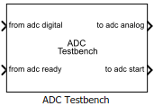
ADC Testbench
Measures DC and AC performance metrics of ADC output
Libraries:
Mixed-Signal Blockset /
ADC /
Measurements & Testbenches
Description
The ADC Testbench block measures both DC and AC performance metrics. DC performance metrics include offset error and gain error. AC performance metrics include signal to noise ratio (SNR), signal to noise and distortion ratio (SINAD), spurious free dynamic range (SFDR), effective number of bits (ENOB), noise floor, and conversion delay.
The ADC Testbench block generates the stimulus to drive the device under test (DUT) from the Stimulus tab. The setup parameters for validating the DUT are defined in the Setup tab and the target validation metrics are defined in the Target Metric tab.
You can use the ADC Testbench block to validate the ADC architectural models provided in Mixed-Signal Blockset™, or you can validate an ADC of your own implementation.
Ports
Input
Digital input signal from the ADC output, specified as a scalar.
Data Types: fixed point | single | double | int8 | int16 | int32 | uint8 | uint16 | uint32 | Boolean
Conversion ready signal from the ADC output, specified as a scalar. This signal indicates when the ADC conversion process is complete.
Data Types: double
Output
Analog output stimulus signal for the ADC input, returned as a scalar.
Data Types: double
External start conversion clock for ADC, returned as a scalar. The rising edge of this signal starts the conversion process in ADC block.
Data Types: double
Parameters
Select whether to measure static (DC) or dynamic (AC) performance metrics.
Select
DCto measure offset error and gain error.Select
ACto measure SNR, SINAD, SFDR, ENOB, noise floor, and conversion delay.
Minimum time for which the simulation must run to obtain meaningful results, specified as a positive real scalar in seconds.
To measure DC performance, the simulation must run so that ADC can sample each digital code until the error tolerance is satisfied. When calculating stop time, the block assumes a minimum of 10 samples per code. You can calculate the expected number of samples (Samples) from error tolerance (ErrorTolerance):
The recommended stop time in this case is:
where SampleInterval is the sample interval of the ADC Testbench and Nbits is the resolution of the ADC, and Hold off time is the defined by the Hold off time parameter.
If there is jitter present in the signal, recommended stop time increases to account for the additional steps required to sample the jittery signal.
Note
If you manually set the sweep range using the Sweep range parameter, you may need to run the simulation longer than the recommended stop time.
So, the Recommended min. simulation stop time (s) T is calculated by using the formula: .
To measure AC performance, the simulation must run so that the ADC can generate 6 spectral updates of the ADC output. The time to generate one spectral output based on Welch's method is given by:
where SamplingFrequency and RBW are the sampling frequency and resolution bandwidth of the spectrum estimator inside the ADC Testbench block.
This parameter is only reported by the testbench and is not editable.
Data Types: double
Click to automatically set the Recommended min. simulation stop time (s) as the stop time of the Simulink® model.
Measure the differential nonlinearity (DNL) error and integral nonlinearity (INL) error using the endpoint method. This method uses the end points of the actual transfer function to measure the DNL and INL error.
Measure the differential nonlinearity (DNL) error and integral nonlinearity (INL) error using the best fit method. This method uses a standard curve fitting technique to find the best fit to measure the DNL and INL error.
Click to plot DC analysis result for further analysis. To perform a complete DC analysis including integral nonlinearity (INL) and differential nonlinearity (DNL), use the ADC DC Measurement block.
Dependencies
This parameter is only available when Measurement option is
set to DC.
Click to store detailed test results to a spreadsheet (XLS file) or as comma-separated values (CSV file) for further processing.
Stimulus
Rate at which the ADC Testbench block polls its input, specified as a positive real scalar in seconds. The testbench reads the input signal and updates the value of its output to control the device under test.
Dependencies
To enable this parameter, set Measurement option as
DC.
Programmatic Use
Block parameter:
SampleInterval |
| Type: character vector |
| Values: positive real scalar |
Default:
1e-6 |
Type of distortion the ADC Testbench block is set to measure,
specified as Harmonic or
Intermodulation.
If the block is calculating the Analog stimulus frequency automatically,
when measuring harmonic distortion, the calculated stimulus frequency is used directly.
when measuring intermodulation distortion, the harmonics are chosen as one tenth above and below the calculated stimulus frequency.
Dependencies
To enable this parameter, set Measurement option as
AC.
Programmatic Use
Block parameter:
DistortionMeasurement |
| Type: character vector |
Values:
Harmonic |
Intermodulation |
Default:
Harmonic |
Frequency of the analog input signal to an ADC block, specified as a positive real scalar in hertz. Analog stimulus frequency must match the input frequency to the ADC device under test. By default, this parameter is calculated automatically. You can deselect Set automatically to customize the value.
If the block is calculating the Analog stimulus frequency automatically,
when measuring harmonic distortion, the calculated stimulus frequency is used directly.
when measuring intermodulation distortion, the harmonics are chosen as one tenth above and below the calculated stimulus frequency.
Analog stimulus frequency must not share any common multiples other than 1 with the Start conversion frequency.
To satisfy this condition, use the equation ,
where:
fanalog is the analog signal frequency,
fstart is the start conversion frequency,
J is the number of cycles of the stimulus per FFT window,
and M is the number of FFT points.
Note
J is selected as the largest prime number less than one tenth of the number of FFT points. The minimum value of M is allowed to be 16.
Dependencies
To enable this parameter, set Measurement option as
AC.
Programmatic Use
Block parameter:
InputFrequency |
| Type: character vector |
| Values: positive real scalar | positive real valued vector |
Default:
98632.8125 |
Resolution bandwidth, specified as a positive real scalar in hertz. This parameter defines the smallest positive frequency that can be resolved. By default, this parameter is calculated automatically. You can deselect Set automatically to customize the value.
Dependencies
To enable this parameter, set Measurement option as
AC.
Programmatic Use
Block parameter:
RBW |
| Type: character vector |
| Values: positive real scalar |
Default:
976.5625 |
Frequency of the start conversion clock of the ADC, specified as a positive real scalar in Hz. Start conversion frequency (Hz) must match the frequency of the start conversion clock of the ADC block.
Programmatic Use
Block parameter:
StartFreq |
| Type: character vector |
| Values: positive real scalar |
Default:
1e6 |
Data Types: double
RMS aperture jitter to be added by the start conversion clock, specified as a positive real scalar in seconds.
Programmatic Use
Block parameter:
RMSJitt |
| Type: character vector |
| Values: positive real scalar |
Default:
40e-12 |
Data Types: double
Maximum allowed difference in the amplitude of the successive samples of the analog input signal, specified as positive real scalar in least significant bit (LSB).
Dependencies
To enable this parameter, set Measurement option as
DC.
Data Types: double
Select to automatically determine the sweep range from the ADC dynamic input range and target metrics. You can deselect this option to specify a custom sweep range.
Dependencies
To enable this parameter, set Measurement option as
DC.
Define a custom sweep range, specified as a 2-element vector.
Dependencies
To enable this parameter, set Measurement option as
DC and deselect the Automatically determine
sweep range parameter.
Data Types: double
Select to stop the simulation on completion. You can deselect this option terminate a simulation early.
Dependencies
To enable this parameter, set Measurement option as
DC.
Setup
Number of physical output bits, specified as a unitless positive real integer in the
range [1, 26]. Number of bits determines the
resolution of the ADC.
Programmatic Use
Use
get_param(gcb,'NBits')to view the current Number of bits.Use
set_param(gcb,'NBits',value)to set Number of bits to a specific value.
Data Types: double
ADC dynamic range, specified as a 2-element row vector in volts.
Programmatic Use
Block parameter:
InputRange |
| Type: character vector |
| Values: 2-element row vector |
Default:
[-1 1] |
Data Types: double
Delays measurement analysis to avoid corruption by transients, specified as a nonnegative real scalar in seconds.
Programmatic Use
Block parameter:
HoldOffTime |
| Type: character vector |
| Values: nonnegative real scalar |
Default:
0 |
Data Types: double
Displays spectrum analyzer during simulation. By default, this option is deselected.
Dependencies
This parameter is only available when Measurement option is
set to AC.
Select to enable increased buffer size during simulation. By default, this option is deselected.
Number of samples of the input buffering available during simulation, specified as a positive integer scalar.
Selecting different simulation solver or sampling strategies can change the number of input samples needed to produce an accurate output sample. Set the Buffer size to a large enough value that the input buffer contains all the input samples required.
Dependencies
This parameter is only available when Enable increased buffer size option is selected in the Configuration tab.
Programmatic Use
Block parameter:
NBuffer |
| Type: character vector |
| Values: positive integer scalar |
Default:
5 |
Data Types: double
Target Metric
Shifts quantization steps by specific value, specified as a positive real scalar in %FS, FS, or LSB.
Note
The full scale range of the converter is defined as the difference between the last and first code on the +0.5 LSB compensated transfer curve. In a +0.5 LSB compensated transfer curve, first code is 0.5 LSB wide while the last code is 1.5 LSB wide. The input values must be considered within the full scale range of the converter.
Note
LSB is calculated by the equation .
Dependencies
To enable this parameter, set Measurement option to
DC.
Programmatic Use
Block parameter:
TargetOffsetError |
| Type: character vector |
| Values: real scalar |
Default:
1.5 LSB |
Data Types: double
Error on the slope of the straight line interpolating ADC transfer curve, specified as a positive real scalar in least significant bit %FS, FS, or LSB.
Note
The full scale range of the converter is defined as the difference between the last and first code on the +0.5 LSB compensated transfer curve. In a +0.5 LSB compensated transfer curve, first code is 0.5 LSB wide while the last code is 1.5 LSB wide. The input values must be considered within the full scale range of the converter.
Note
LSB is calculated by the equation .
Dependencies
To enable this parameter, set Measurement option to
DC.
Programmatic Use
Block parameter:
TargetGainError |
| Type: character vector |
| Values: real scalar |
Default:
1 LSB |
Data Types: double
Version History
Introduced in R2019a
See Also
ADC DC Measurement | ADC AC Measurement | Flash ADC | SAR ADC | Spectrum Analyzer
MATLAB Command
You clicked a link that corresponds to this MATLAB command:
Run the command by entering it in the MATLAB Command Window. Web browsers do not support MATLAB commands.
Sélectionner un site web
Choisissez un site web pour accéder au contenu traduit dans votre langue (lorsqu'il est disponible) et voir les événements et les offres locales. D’après votre position, nous vous recommandons de sélectionner la région suivante : .
Vous pouvez également sélectionner un site web dans la liste suivante :
Comment optimiser les performances du site
Pour optimiser les performances du site, sélectionnez la région Chine (en chinois ou en anglais). Les sites de MathWorks pour les autres pays ne sont pas optimisés pour les visites provenant de votre région.
Amériques
- América Latina (Español)
- Canada (English)
- United States (English)
Europe
- Belgium (English)
- Denmark (English)
- Deutschland (Deutsch)
- España (Español)
- Finland (English)
- France (Français)
- Ireland (English)
- Italia (Italiano)
- Luxembourg (English)
- Netherlands (English)
- Norway (English)
- Österreich (Deutsch)
- Portugal (English)
- Sweden (English)
- Switzerland
- United Kingdom (English)