Simulate Stability Assistance Algorithm Using Gazebo Simulator for VEX V5 Robot
This example shows how to model a robot's control algorithm in Simulink® and simulate the robot using Gazebo simulator. A VEX® V5 Robot is preconfigured in Gazebo Simulator along with a virtual world. The control algorithm is modeled in Simulink and the model is interfaced using Gazebo Co-simulation blocks. This example also allows you to perform stability assistance while lifting heavy objects using feedback from an IMU sensor.
Setup Gazebo Simulation Environment
To run this example, download and set up the preconfigured Virtual Machine with ROS and Gazebo. For more information, see Set Up Gazebo Simulation Environment. In the Setup Gazebo Simulation Environment topic, perform the steps listed in these topics.
Set Up and Run Simulink Model
1. Open the vexv5_clawbot_gazebo preconfigured Simulink example model.
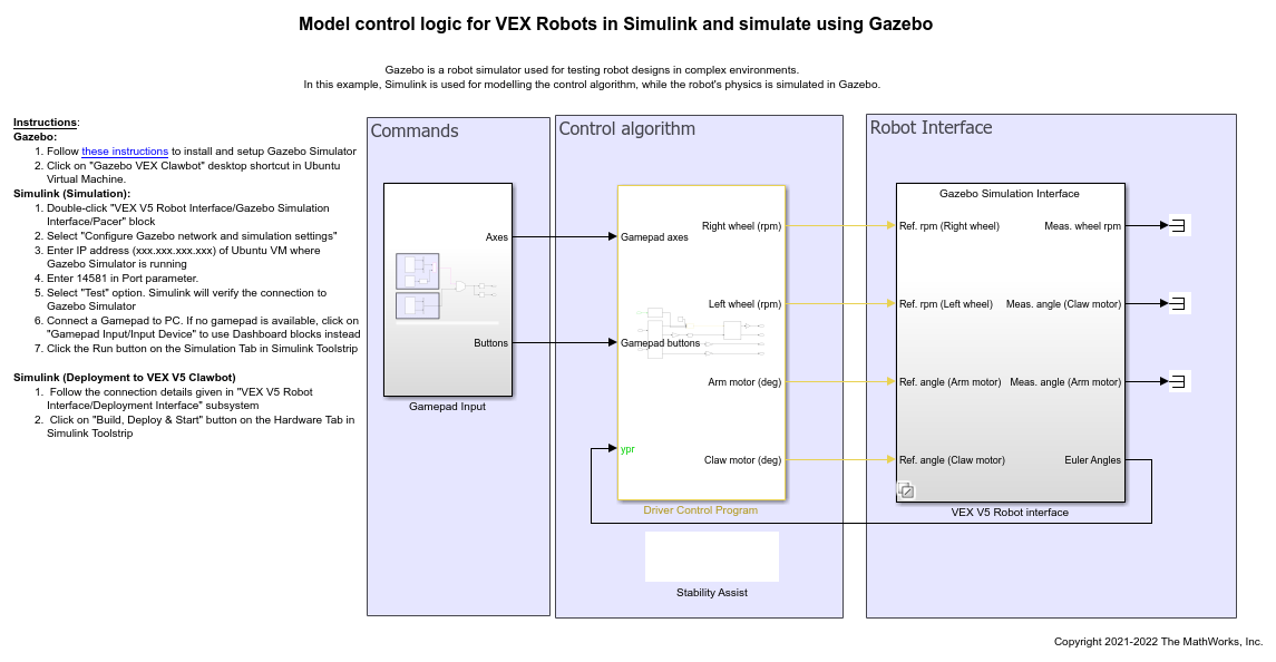
2. Navigate to VEX V5 Robot interface/Gazebo Simulation Interface subsystem and Open Gazebo Pacer block.
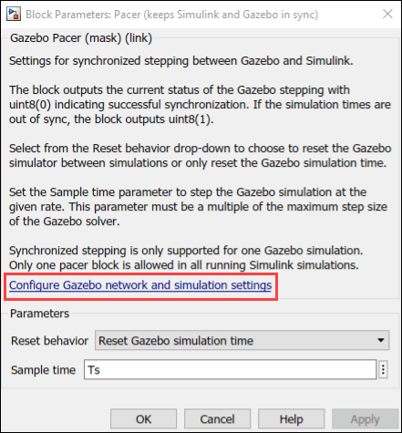
3. Click on Configure Gazebo network and simulation settings link. Enter the Virtual Machine IP Address. Set the Port to 14581.

4. Click Test connection to verify the connection to Gazebo model. Click Ok and close the block dialog.
5. Gamepad configuration: This example simulates manual joystick control of VEX Robot. Perform these steps to configure the gamepad.
a Navigate to Gamepad Input/Gamepad/Joystick input.
b. Open Gamepad simulator block.

c. If you are using VEX Gamepad or Logitech Gamepad, select Logitech Gamepad. Change the type if you are using Xbox controller.
d. For other joystick brands, use Joystick Input block from Simulink 3D animation.
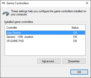
e. Joystick ID is 1 when there is only one joystick connected to the PC. If there are multiple joysticks or virtual joysticks, then Joystick ID needs to be set correctly. Search for "Set up USB game controllers" in start menu and open it. This entry number corresponds to Joystick ID.
f. If joysticks are not available, double click on Input Device Variant Source block to use Dashboard blocks (Gamepad Input/Dashboard control) for controlling the robot.
Note: Only the used buttons/sliders are active during simulation. Unconnected buttons are removed from the simulation.
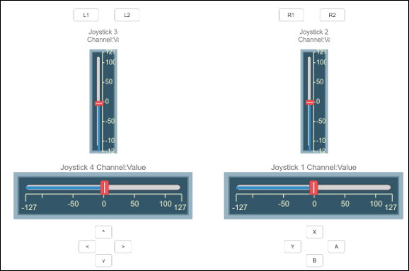
6. Click Run from the Simulation pane. Joystick axes (3,4) are used for drive control. Arm, and Claw control are mapped to buttons X and A respectively.
Control Logic
Driver Control Program subsystem takes inputs from Joystick and gives commands to wheel motors (rpm), Arm and Claw motors as shown in this screen.
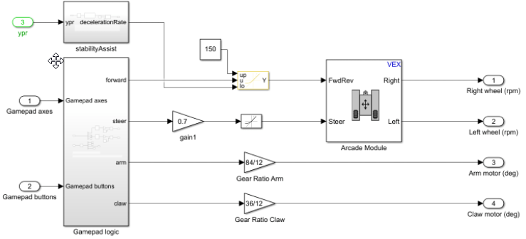
Arcade Module block is used to convert forward and steering input to left and right wheel speeds. Rate Limiter block prevents sudden changes in wheel speeds and makes motion smooth. Arm and Claw angles are scaled with respective gear ratios before sending to motors.
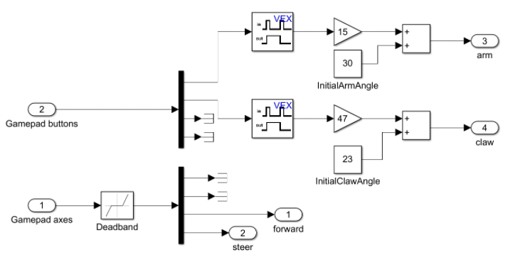
Inside Gamepad logic subsystem, some of the axes (X,Y) and buttons are mapped to control the driving, arm and claw. Latch block is used to hold the signal when buttons are released from Gamepad.
Stability Assistance Logic
While picking heavy objects, the center of gravity might shift closer to edge of robot base. In these cases, any sudden acceleration (while starting or stopping) in the robot might tip the robot over.

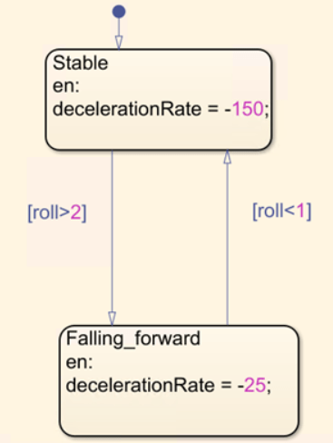
This issue can be partly tackled using better programming logic. In this example, the angle feedback from IMU sensor is used to detect when the robot begins to tip over. If the robot begins to tip, deceleration limit is lowered. This prevents the robot from stopping suddenly and falling over.

The Stateflow® chart has two states, Stable and Falling_forward. Robot starts in Stable state and switches over if angle crosses a certain threshold.
