End-to-End DVB-RCS2 Simulation with RF Impairments and Corrections for TC-LM and CC-CPM Bursts
This example shows how to measure the packet error rate (PER) of a Digital Video Broadcasting - Return Channel by Satellite second generation (DVB-RCS2) link that has a constant waveform ID for either Turbo-Coding Linear Modulation (TC-LM) or Convolutional-Coding Continuous Phase Modulation (CC-CPM) reference bursts. The example describes the burst detection and frequency synchronization strategies in detail, emphasizing how to estimate the radio frequency (RF) front-end impairments under noise conditions. In this example, you add RF front-end impairments and then pass it through an additive white Gaussian noise (AWGN) channel.
Introduction
DVB-RCS2 defines the physical layer interface and medium access control layer functionalities required to provide broadband connectivity for an interactive satellite network between the satellite hub operator and user terminals. The standard specifies powerful duo-binary turbo codes (TC-LM and SS-TC-LM modes) and convolutional encoding (CC-CPM mode) for forward error control (FEC), and cyclic redundancy checks (CRC) for error detection and correction.
ETSI EN 301 545-2 V1.3.1 Annex A table A-1 summarizes the TC-LM reference burst waveforms for different modulation schemes and code rates. The receiver uses the DVB-S2X forward link to derive information about the reference waveform used for a specific timeslot. The receiver uses this information to perform the burst detection and frequency synchronization by exploiting the known symbols in the burst. The variety of waveforms and their characteristics make burst detection and frequency synchronization a challenging task.
This diagram summarizes the example workflow.

Main Processing Loop
The example processes 200 TC-LM bursts with Es/No of 15.5 dB, and then computes the number of packet errors. The comm.PhaseFrequencyOffset object adds a carrier frequency offset to the modulated signal, and the awgn function adds AWGN. The DVB-RCS2 standard allows frequency offset values of up to 3% of the symbol rate.
To recover the protocol data unit (PDU), the receiver performs matched filtering, synchronization operations, and bit recovery. The receiver uses the known symbol sequences, such as the preamble, postamble, and pilots, to perform the burst detection. The receiver derives the physical layer transmission parameters, such as modulation scheme, code rate, and turbo decoder parameters, from the waveform ID.
The network control centre performs a Multi-Frequency Time-Division mutiple access (MF-TDMA) based resource allocation. First, the control centre assigns multiple slots to every terminal for transmission. The DVB-RCS2 terminal (RCST) transmits a number of bursts for each interval. Each burst contains a PDU. The waveform generator appends CRC bits to the PDU. The content type of the burst determines the number of CRC bits appended to the burst. The receiver recovers the data bits and the CRC status from the waveform symbols. This example uses the CRC status of all the decoded bursts to measure the number of packet errors.
DVB-RCS2 Waveform Configuration Parameters
Specify these burst waveform configuration parameters.
Waveform ID
Content type of PDU
Pre-burst guard length
Post-burst guard length
This example supports only the TC-LM reference burst waveform IDs, which are in the ranges [1, 22] and [32, 49]. Apply the same configuration to the receiver object dvbrcs2RecoveryConfig.
% Waveform Generator parameter initialization wg = dvbrcs2WaveformGenerator; wg.TransmissionFormat ="TC-LM"; wg.ContentType =
"traffic"; wg.WaveformID = 21; % Guard interval specified as number of symbols wg.PreBurstGuardLength= 0; wg.PostBurstGuardLength = 0; % View waveform generator information wg.info
ans = struct with fields:
              BurstLength: 1616
     PayloadLengthInBytes: 539
            MappingScheme: "16QAM"
                 CodeRate: "3/4"
           PreambleLength: 10
          PostambleLength: 9
              PilotPeriod: 10
         PilotBlockLength: 1
    PermutationParameters: [65 0 3 7 0]
               UniqueWord: "444E4EE4EEE4EEEE4E44"
                 PilotSum: 159
% Initialize the receiver properties using the waveform properties based on
% the transmission format
if strcmp(wg.TransmissionFormat,"TC-LM")
    cfg = dvbrcs2RecoveryConfig;
    cfg.TransmissionFormat = wg.TransmissionFormat;
    cfg.WaveformID = wg.WaveformID;
    cfg.ContentType = wg.ContentType;
    cfg.NumDecodingIterations = 8;
else
    cfgCPM.WaveformID = wg.WaveformID;
    cfgCPM.ContentType = wg.ContentType;
    cfgCPM.DemodulatorTracebackDepth = 16;
    cfgCPM.SerialSISOIterations = 16;
    cfgCPM.SamplesPerSymbol = wg.SamplesPerSymbol;
end

% Initialize the random number generator with an arbitrary seed
rng(52);
Simulation Parameters
The DVB-RCS2 standard supports flexible channel bandwidths. This example selects an arbitrary channel bandwidth value of 1.2 MHz, which corresponds to 1 megasymbols per second. The frequency synchronization algorithm in this example can track carrier frequency offsets (CFOs) up to 10 kHz. The symbol rate is equal to B/(1+R), where B is the channel bandwidth, and R is the roll-off factor. Set the roll-off factor to 0.2, as defined in ETSI EN 301 545-2 V1.3.1 section 7.3.7.1.1. Set the carrier frequency to 14.5 GHz, and the fixed CFO contribution to 1590 Hz, as defined in ETSI EN TR 101 545-4 V1.1.1 section 10.1.2. Specify the RCST terminal type as "Fixed", "Pedestrian", or "Vehicular". This example derives the corresponding velocity value of the terminal from ETSI EN TR 101 545-4 V1.1.1 section 6.2.1 table 6.1, and uses the terminal type to calculate the CFO contributed by the terminal motion. The RCST may have the functionality to perform Doppler precompensation if it has the appropriate equipment to calculate its position and velocity.
Select the Es/No from ETSI EN TR 101 545-4 V1.1.1 section 10.2.1 table 10.5. To obtain a PER of , you must specify a higher Es/No value.
% Samples per symbol simParams.sps = wg.SamplesPerSymbol; % Number of bursts to be processed simParams.numBursts = 200; % Channel bandwidth in Hertz simParams.chanBW = 1.2e6; % Select the type of terminal that is transmitting the DVB-RCS2 signal simParams.RCSTType ="Fixed"; simParams.HasDopplerPrecompensation = true; simParams.carrierFreq = 14.5e9; % CFO in Hz simParams.cfoFixedContribution = 1590; % Velocity in meters per second if strcmp(simParams.RCSTType,"Fixed") velocity = 0; elseif strcmp(simParams.RCSTType,"Pedestrian") velocity = 1.38; elseif strcmp(simParams.RCSTType,"Vehicular") velocity = 33.33; end speedLight = physconst("LightSpeed"); % Doppler shift in Hz dopplerShift = velocity*simParams.carrierFreq/speedLight; % Energy per symbol to noise ratio in decibels simParams.EsNodB = 15.5; sps = wg.SamplesPerSymbol;
Initialize the comm.PhaseFrequencyOffset System object and Doppler precompensation object.
% Carrier phase and frequency offset addition
if strcmp(wg.TransmissionFormat,"TC-LM")
    rolloffFactor = 0.2;
    symbolRate = simParams.chanBW/(1 + rolloffFactor);
    sampleRate = symbolRate*simParams.sps;
else
    %Spectral efficiency values for different waveform IDs
    spectralEfficiencyList = [0.5 0.5 0.5 0.75 1.1 1.25 1.5 1.8 0.5 ...
        0.75 1.1 1.25 1.5 1.8 0.5 0.75 1.1 1.25 1.5 1.8];
    symbolRate = simParams.chanBW * spectralEfficiencyList(wg.WaveformID);
    sampleRate = symbolRate*simParams.sps;
end

% Initialize the frequency offset system object
freqOffset = comm.PhaseFrequencyOffset( ...
        FrequencyOffset=simParams.cfoFixedContribution+dopplerShift, ...
        SampleRate=sampleRate);

% Initialize the Doppler precompensation object
if simParams.HasDopplerPrecompensation
    % Specify the frequency value to precompensate prior to transmission
    precompensationFreq = -dopplerShift;
    dopplerPrecompensator = comm.PhaseFrequencyOffset( ...
        FrequencyOffset=precompensationFreq, ...
        SampleRate=sampleRate);
end
Synchronizer Initialization
The receiver performs these operations on the received data, in sequence:
Burst detection
Carrier frequency offset estimation and compensation
Bit recovery
This diagram illustrates the sequence of the receiver operations.

The burst detection and frequency synchronization algorithms are variations of differential correlation. The burst detection algorithm identifies the start of each individual burst, and discards any initial junk symbols. The frequency offset estimation reduces the frequency offset to a level that does not affect the performance of the bit recovery algorithms.
The burst detection uses preamble sequences to identify the start of bursts. To achieve better accuracy, the receiver first buffers several bursts. The synchronizer object HelperDVBRCS2Synchonizer applies a differential correlator to the buffered samples and averages the result over a single burst interval.
Because the correlation between the noisy, adjacent samples is not ideal, a decrease in the Es/No value affects the performance of the differential correlator. This makes averaging over multiple bursts essential.
For TC-LM bursts, the receiver carries out the CFO estimation using the pilots present in the burst. Differential correlation, with pilot period as the correlation interval, leads to a reliable estimate of the CFO under lower noise conditions. As the number of pilots increases, the accuracy of the CFO estimate improves. You can change the number of bursts for synchronization based on the waveform ID, such as reducing the number of bursts required for synchronization for waveforms with larger preambles, higher numbers of pilots symbols, or a postamble sequence. For more information on the minimum number of bursts for synchronization for each waveform ID, see the table in the Further Exploration section. For CC-CPM bursts, a window-based auto-correlator is used to detect the preamble and midamble sequences embedded in the waveform for burst detection and frequency offset estimation.
Specify the waveform ID, symbol rate, number of bursts for synchronization, pre-burst and post-burst guard lengths, filter span (in symbols) for TC-LM bursts, and samples per symbol to HelperDVBRCS2Synchonizer.
numBurstsForSync = 9;
freqSynchronizer = HelperDVBRCS2Synchronizer( ...
    TransmissionFormat = wg.TransmissionFormat,...
    WaveformID=wg.WaveformID, ...
    SymbolRate=symbolRate, ...
    NumBurstsForSynchronization=numBurstsForSync, ...
    PreBurstGuardLength=wg.PreBurstGuardLength, ...
    PostBurstGuardLength=wg.PostBurstGuardLength, ...
    SamplesPerSymbol=wg.SamplesPerSymbol);
if strcmp(wg.TransmissionFormat,"TC-LM")
    freqSynchronizer.FilterSpanInSymbols=wg.FilterSpanInSymbols;
end
Visualization
Initialize the scope objects required to visualize various stages of the main processing loop.
rxConst = comm.ConstellationDiagram(Title="Frequency Shifted waveform", ...
    AxesLimits=[-1 1], ...
    ShowReferenceConstellation=false, ...
    SamplesPerSymbol=wg.SamplesPerSymbol);

specAn = spectrumAnalyzer(SampleRate=sampleRate, ...
    ChannelNames={'Transmitted waveform','Received waveform'}, ...
    ShowLegend=true);
Receiver Processing
To synchronize the received burst and recover the PDU, the receiver processes distorted DVB-RCS2 waveform samples one burst at a time by following these steps.
Apply matched filtering, outputting at a rate of one sample per symbol (for TC-LM bursts only).
Buffer the required number of bursts into the synchronizer.
Perform burst detection using differential correlation.
Estimate and apply frequency offset correction.
Estimate and compensate for residual carrier frequency offset.
Perform bit recovery and verify integrity of a PDU using the CRC status.
% Initialize the count for the packet errors
pduErrTotal = 0;
% Preallocate memory for the vector containing individual frequency
% estimates post reception of each burst
estimatedFreqOffsetVector = zeros(simParams.numBursts,1);

% Main processing loop
for burstIndex = 1:simParams.numBursts
    % Generate a frame protocol data unit
    framePDU = randi([0 1],wg.FramePDULength,1);
    % Generate a complex baseband frame
    txOutTemp = wg(framePDU);

    % Apply carrier frequency offset
    txOut = freqOffset(txOutTemp);
    % Apply Doppler precompensation, if applicable
    if simParams.HasDopplerPrecompensation
        cfoOut = dopplerPrecompensator(txOut);
    else
        cfoOut = txOut;
    end
    % Visualize the frequency offset waveform
    rxConst(cfoOut(1:length(txOutTemp)))

    % To simulate a receiver which has been switched on early, we prepend
    % extra symbols to the first burst for the timeslot
    if burstIndex == 1
        maxNumNoiseSymbols = 250;
        numNoiseSymbols = randi(maxNumNoiseSymbols,1,1)*sps;
        rxIn = awgn([zeros(numNoiseSymbols,1); cfoOut(:)], ...
            simParams.EsNodB - 10*log10(simParams.sps),"measured");
    else
        rxIn = awgn(cfoOut(:),simParams.EsNodB - 10*log10(simParams.sps),"measured");
    end
    % Frequency analysis between transmitted and received signal
    specAn([txOutTemp rxIn(1:length(txOutTemp))]);
    % Synchronization frequencies
    [compensatedWaveform,syncIndex, ...
        estimatedFreqOffset,numBurstsProcessed] = freqSynchronizer(rxIn);
    if numBurstsProcessed > freqSynchronizer.NumBurstsForSynchronization
        % Bit recovery
        estimatedFreqOffsetVector(burstIndex,:) = estimatedFreqOffset;
        if strcmp(wg.TransmissionFormat,"TC-LM")
            [rxOut,pduErr] = ...
                dvbrcs2BitRecover(compensatedWaveform,cfg,10^(-simParams.EsNodB/10));
        else
            [rxOut,pduErr] = ...
                HelperDVBRCS2CCCPMModeBitRecover(compensatedWaveform,cfgCPM,10^(-(simParams.EsNodB - 10*log10(simParams.sps))/10));
        end
        if logical(pduErr)
            pduErrTotal = pduErrTotal + 1;
        end
    end
end


if simParams.numBursts > freqSynchronizer.NumBurstsForSynchronization
    disp("Number of bursts lost: " + num2str(pduErrTotal));
    disp("PER = " + num2str(pduErrTotal/(simParams.numBursts - freqSynchronizer.NumBurstsForSynchronization)));
end
Number of bursts lost: 0
PER = 0
Further Exploration
This example has shown you how to decode TC-LM bursts with a waveform ID of 21 at an Es/No value of 15.5 db. Try running this example with these modifications.
Change waveform ID to other valid values to generate different TC-LM waveforms.
Change transmission format to CC-CPM and decode bursts with waveform IDs in the range [1,20].
Vary Es/No and observe the performance of the synchronizer.
Disable Doppler precompensation and observe the performance of the receiver for different Es/No values.
Change the terminal type to change the velocity profile of the RCST.
Vary the fixed frequency offset component to observe the effects on the transmitted waveform.
Vary the velocity values of the different RCST types, and try to observe the frequency offset constellation plot.
Vary the frequency value used for frequency precompensation, and run the example to observe whether the receiver is capable of handling residual frequency errors.
Change the synchronizer configuration to use a different number of bursts.
Change the seed value of the random number generator to obtain different values for the number of junk symbols, the payload sequences, and the AWGN channel simulations.
Use this table to select the simulation parameters for TC-LM bursts.
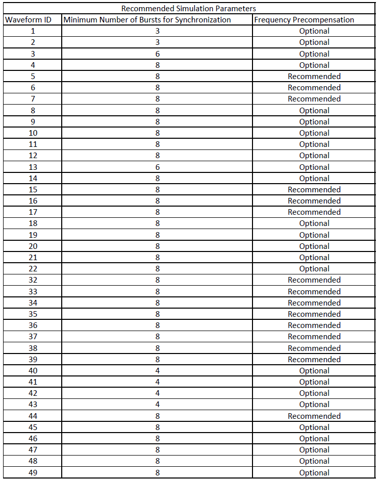
For CC-CPM bursts, all bursts have the same symbol sequence for the preamble and midamble. Based on several simulations, it is recommended to use at least 8 bursts for synchronization.
The CC-CPM demodulator supports C/C++ code generation, which enhances the execution speed of HelperDVBRCS2CCCPMModeBitRecover. To generate C/C++ code, run the following command in the command window.
% codegen HelperRCS2APPDemodulate -args {coder.typeof(1+i,[Inf 1]), coder.typeof(uint32(1),[1 1]), coder.typeof(uint32(1),[1 1]),coder.typeof(uint32(1),[1 1]),coder.typeof(uint32(1),[1 1]),coder.typeof(uint32(1),[1 1]),coder.typeof(uint32(1),[1 1]),coder.typeof(logical(1),[1 1]),coder.typeof(uint32(1),[1 1]),coder.typeof(uint32(1),[Inf 1]),coder.typeof(1,[Inf 1]),coder.typeof(1,[Inf 1]), coder.typeof(1,[Inf 1]),coder.typeof(1,[Inf Inf]),coder.typeof(1,[1 1]),coder.typeof(1,[Inf 1])}Once code generation is complete, replace all instances of HelperRCS2APPDemodulate in HelperDVBRCS2CCCPMModeBitRecover with HelperRCS2APPDemodulate_mex.
Appendix
The example uses these helper functions:
HelperDVBRCS2Synchonizer.m: Perform matched filtering, burst detection, and carrier frequency offset estimation and correctionHelperDVBRCS2CCCPMModeBitRecover.m: Perform CC-CPM mode demodulation, decoding, and bit recoveryHelperRCS2APPDemodulate.m: Perform CC-CPM burst demodulation
References
ETSI EN 301 545-2 V1.2.1 (2014-04), DVB-RCS2 Lower Layer Satellite Specification.
ETSI TS 101 545-1 V1.3.1 (2020-07), DVB-RCS2 System Level Specification