Custom Gear Library
This example shows how to use the custom Simscape™ Gear Library to build and analyze different gear‑train configurations, ranging from a simple gear pair to planetary and differential systems. The library provides a graphical, component‑level way to model gear mechanisms so that your Simscape diagram closely resembles a traditional gear stick diagram. The gear stick diagram is a side‑view representation where gear axes lie in the plane of the Simulink® canvas.
Use this library when you want a concrete, part‑level representation of gears and meshes. Each gear block represents a physical component that you can use to describe geometry, inertia, losses, and loads in detail.
The blocks in the Gear Library track:
Rotation of each gear about the X‑ or Y‑axis
Translational velocity of the gear's pitch radius
You can model each gear mesh as ideal or with ordinary efficiency, which captures loss effects where appropriate. To connect the gear train to other rotational elements or applied loads, use an Interface block.
This example shows five increasingly complex configurations to illustrate how to assemble and parameterize gear models:
Simple Gear Pair
Sun-Planet Gear
Beveled Sun-Planet Gear
Planetary Gear
Differential Gear
Open the CustomGearLibraryDifferentialGear system.
open_system('CustomGearLibraryDifferentialGear');
Concepts for Using the Gear Library
Diagram Symbols
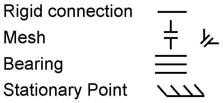
The custom Gear Library uses four key symbols to show how components connect in the gear stick-style diagrams:
Single line — a rigid connection between components.
Two parallel lines — a gear mesh (spur or bevel). For bevel gears, the connected rigid lines meet at 90°.
Three parallel lines — a bearing (revolute joint).
Slanted tick marks on a line — a stationary point.
Block Ports and Connections
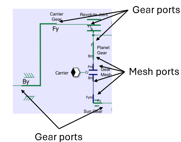
Blocks in the Gear Library use two port types, Gear ports and Mesh ports. Each port can only connect to ports of the same type.
Gear Ports
Gear ports belong to the Gear domain, representing rigid connections between parts.
You can connect multiple Gear ports at one node in the Gear network.
You can connect only Gear ports to other Gear ports.
Gear‑domain ports use labels: B, Bx, By, F, Fx, Fy.
Mesh Ports
Mesh ports belong to the Mesh domain, representing gear‑tooth contact.
A valid mesh connection is exactly one Mesh port to one Mesh port.
You cannot connect more than two Mesh ports together.
Mesh‑domain port labels include an "m": Bm, Bxm, Bym, Fm, Fxm, Fym.
The x or y suffix in the label refers to block orientation.
This image shows part of a Gear network where the arrows indicate which ports are Gear ports and which ports are Mesh ports.
Directions
To use the Custom Gear Library, you must align the block internal directions with the network directions.
Network Directions
Blocks in the Gear Library use directional port labels that use B for "Base" and F for "Follower". For consistent sign conventions of forces, torques, and translational velocities, align all blocks on the canvas so their B→F directions match a common set of X- and Y-directions in your model.
To define these directions:
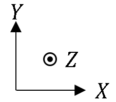
Choose any direction on the canvas as the network X-direction: left, right, up, or down.
Define the network Y-direction as perpendicular to the X-direction on the canvas.
Use the right-hand rule to determine the network's Z-direction, where the Z-axis points into or out of the canvas.
Once you choose the canvas X- and Y-directions, add a small direction arrow graphic to the canvas showing +X, +Y, and +Z for reference, like the one shown below.
Block Internal Directions
Each block also has its own internal B→F directions that you must align with the network directions for consistent signs of torque and force.
Bx → Fx or Bxm → Fxm represents the internal X-direction of the block. Align this with the network X-direction.
By → Fy or Bym → Fym represents the internal Y-direction of the block. Align this with your network Y-direction.
B → F or Bm → Fm represents a direction that can correspond to either the network X- or Y-direction. Align this direction with the desired network direction.
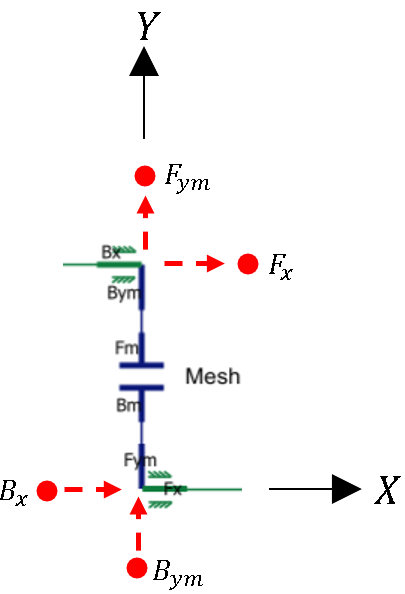
For clean diagram appearance, you can hide unused ports. Hiding a port does not change the internal direction of the block. The B side is always opposite the F side. Even when ports are hidden, visualize the B→F direction and ensure it matches the network direction that you intend.
The green and blue lines in this image are part of a Gear network. The red circles indicate hidden ports. The red arrows indicate the block internal directions that are aligned with the network direction.
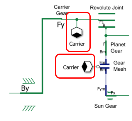
Mesh Losses
You can use the Gear Mesh and Bevel Gear Mesh blocks to model either an ideal mesh or a mesh with a constant ordinary efficiency. You can specify different ordinary efficiencies for different power flow directions through the mesh.
To learn more about the loss model, see Model Gears with Losses.
If the mesh includes a planet gear, meaning a gear whose axis moves with a carrier, you must select the One or both gears are on a carrier parameter.
When you select the One or both gears are on a carrier parameter, the Mesh block adds a Cr port. To keep the diagram tidy, use a Connection Label block so you can route the carrier connection without any lines on the Simulink canvas because there is not a direct physical connection. Through the Cr port, the Mesh block senses the angular velocity of the carrier and applies a torque loss to the carrier, which the block uses to determine the power inefficiency. If you skip the carrier connection, the model computes incorrect frictional power losses whenever the carrier rotates.
This image shows a Gear Mesh block with a Cr port. The Connection Label blocks, labeled Carrier, connect the Cr port to a port of the Carrier Gear block.
Limitations
In the Gear domain, a Translational Spacer block connected to a Gear Mesh or Bevel Gear Mesh block represents the entire gear radius. You cannot divide the gear radius among multiple spacer blocks. This requirement exists because the mesh model uses the torque applied at the full radius to calculate power losses correctly. This situation typically arises when modeling a crown gear and carrier in a differential.
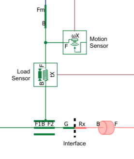
Interface and Sensor Blocks
Use an Interface block to connect the gear network to angle‑based rotational elements such as Inertia (AB), Rotational Damper (AB), actuators, or loads. You can also connect to translational components like Mass or Translational Damper blocks. Any hidden port on an Interface block acts as a free node for that direction.
To monitor what happens inside the gear network, use Load Sensor and Motion Sensor blocks.
The Load Sensor block reports force and torque and behaves like a rigid link in all motion directions. Connect the Load Sensor block in series with the part of the network that you want to measure.
The Motion Sensor block measures rotational motion or translational velocity. When you set Measurement reference parameter to
Difference, connect the Motion Sensor block in parallel to the part of the network that you want to measure.
This image shows a Load Sensor block, a Motion Sensor block with the Measurement reference parameter set to Absolute, and an Interface block with the Rx port enabled.
Simple Gear Pair
The simple Gear Pair model contains two gears with fixed rotational axes. The stick diagram and Simscape Gear network are both oriented so that the X-direction points to the right, the Y-direction points up, and the Z-direction points out of the Simulink canvas.
Open the Simple Gear Pair model.
open_system('CustomGearLibrarySimpleGearPair');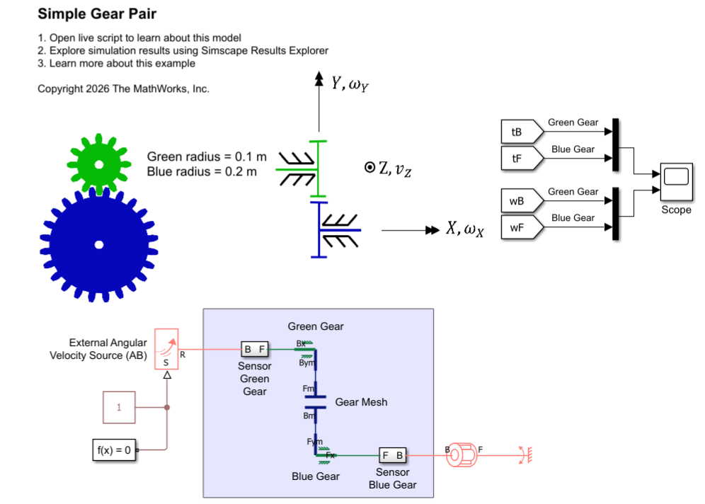
The sensor subsystems each contain a Rotational Motion Sensor (AB) block for sensing angular velocity and a Torque Sensor (AB) block for sensing torque. The sensor subsystems are oriented so that the F port is closer to the gear, causing the sensor to measure torque from the rotational network acting on the gear shaft.
The governing equations for this system are:
where:
represents the base shaft, attached to the red gear.
represents the follower shaft, attached to the green gear.
and are the gear radii.
and are the gear angular velocities.
and are the torques applied by the rotational network on the gear shafts.
is the friction loss torque.
Open the Scope block and simulate the model.
open_system('CustomGearLibrarySimpleGearPair/Scope');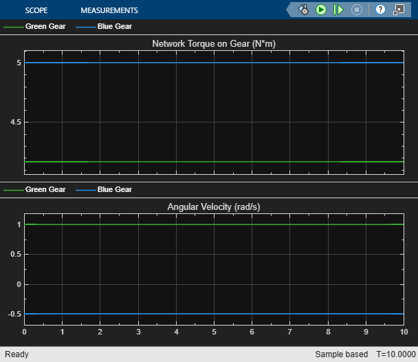
sim('CustomGearLibrarySimpleGearPair');Close the model.
close_system('CustomGearLibrarySimpleGearPair/Scope', 0);Sun-Planet Gear
The Sun-Planet Gear model contains a sun gear and a planet gear on a carrier.
The model uses a Revolute Joint block and Translational Spacer block, labeled Planet Gear, to represent the planet gear because they enable torsional load transfer at the planet gear shaft.
Open the model.
open_system('CustomGearLibrarySunPlanetGear');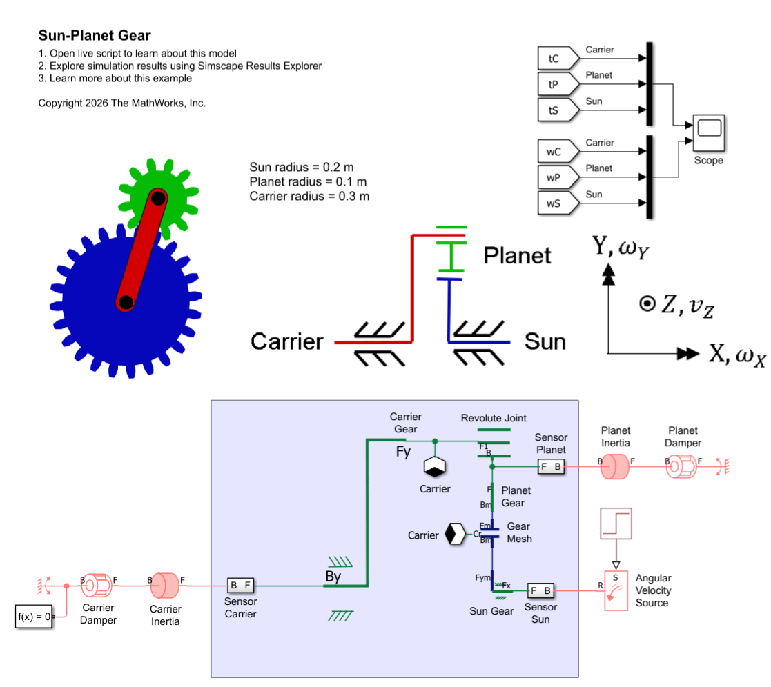
The governing equations for this system are:
where:
represents the carrier gear.
represents the sun gear.
represents the planet gear.
and are the gear radii.
and are the gear angular velocities, or spin velocities.
, and are the torques applied by the rotational network on the gear shafts.
is the friction loss torque.
Open the Scope block and simulate the model.
open_system('CustomGearLibrarySunPlanetGear/Scope');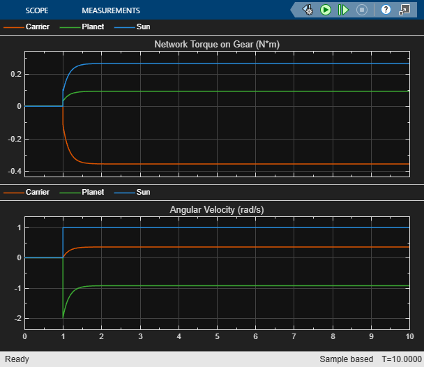
sim('CustomGearLibrarySunPlanetGear');Close the model.
close_system('CustomGearLibrarySunPlanetGear/Scope', 0);Beveled Sun-Planet Gear
The Beveled Sun-Planet Gear model contains a sun gear and a planet gear arranged as a bevel gear pair with perpendicular axes.
Open the model.
open_system('CustomGearLibraryBeveledSunPlanetGear');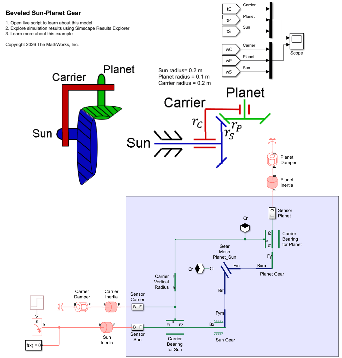
The governing equations for this system are:
where:
represents the carrier gear.
represents the sun gear.
represents the planet gear.
and are the gear radii.
and are the gear angular velocities, or spin velocities.
, and are the torques applied by the rotational network on the gear shafts.
is the friction loss torque.
Open the Scope block and simulate the model.
open_system('CustomGearLibraryBeveledSunPlanetGear/Scope');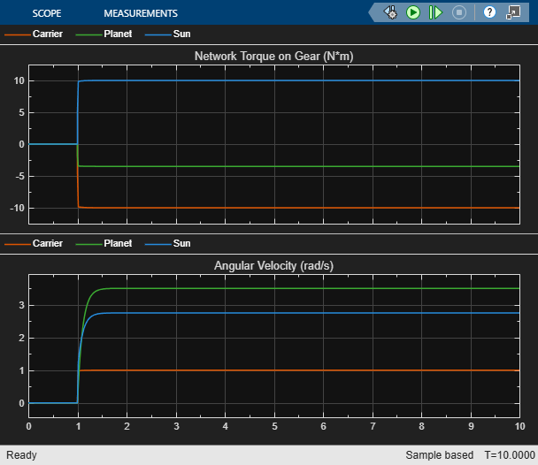
sim('CustomGearLibraryBeveledSunPlanetGear');Close the model.
close_system('CustomGearLibraryBeveledSunPlanetGear/Scope', 0);Planetary Gear
The Planetary Gear model represents a gear train with sun, planet, and ring gears. Planetary gears are common in transmission systems, where they provide high gear ratios in compact geometries.
Open the model.
open_system('CustomGearLibraryPlanetaryGear');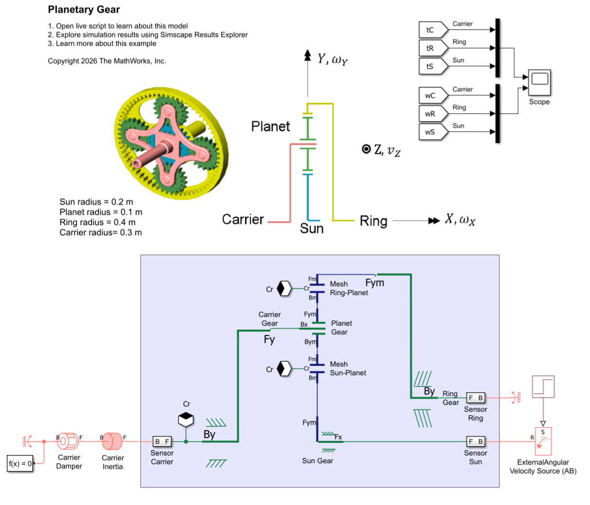
The ideal governing equations for this system are:
Torque loss occurs due to friction at the Sun-Planet mesh and Ring-Planet mesh.
where:
represents the carrier gear.
represents the sun gear.
represents the planet gear.
represents the ring gear.
and are the gear radii.
and are the gear angular velocities, or spin velocities.
and are the torques applied by the rotational network on the gear shafts.
Open the Scope block and simulate the model.
open_system('CustomGearLibraryPlanetaryGear/Scope');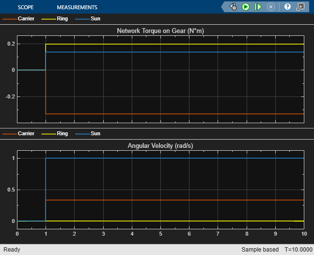
sim('CustomGearLibraryPlanetaryGear');Close the model.
close_system('CustomGearLibraryPlanetaryGear/Scope', 0);Differential Gear
The Differential model represents an open differential gear mechanism. Differentials are common in automobiles, where they enable the various wheels to spin at different speeds while cornering.
Open the model.
open_system('CustomGearLibraryDifferentialGear');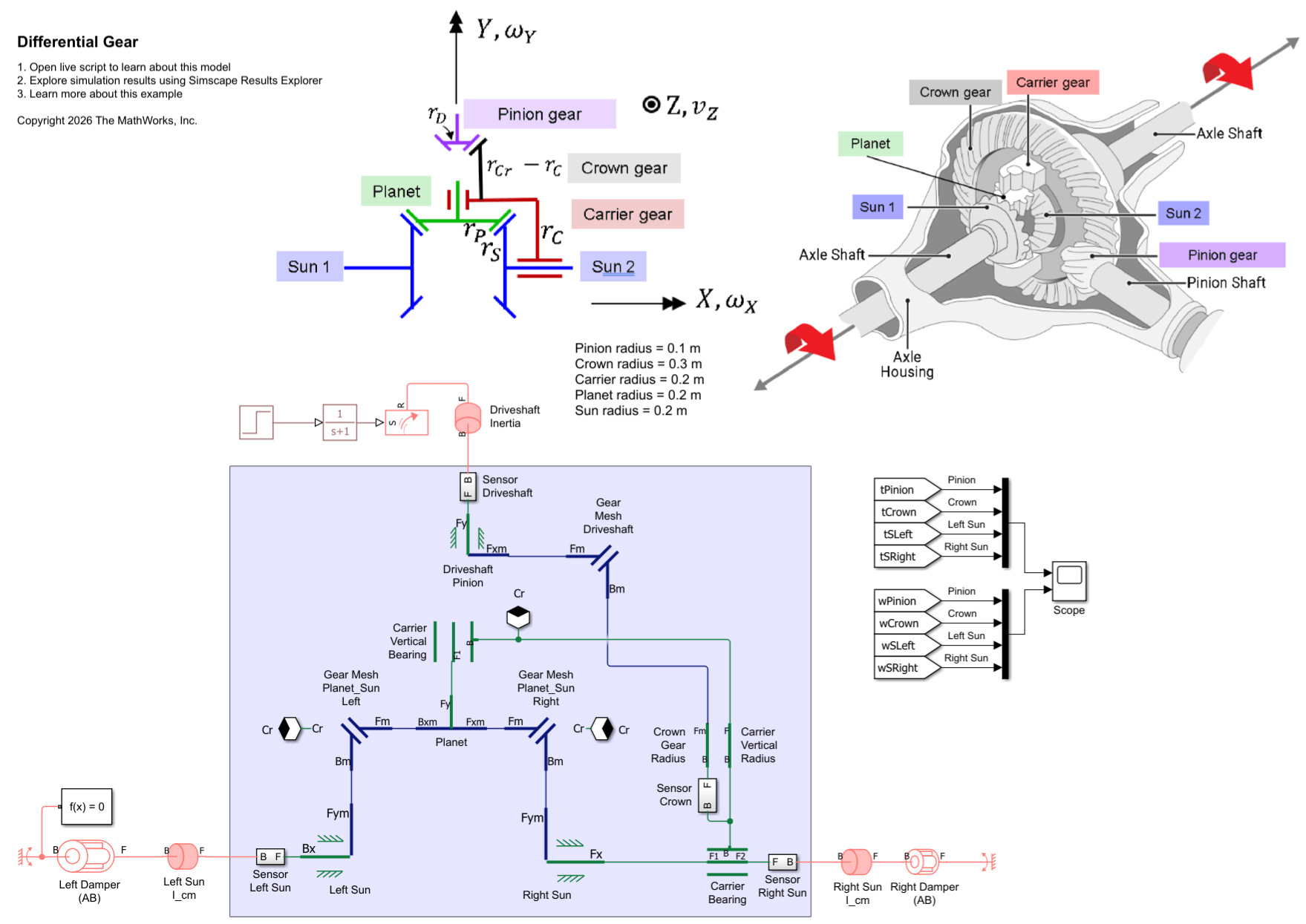
This model represents an open differential with a load imbalance. The Left Damper (AB) block has a greater value for the Damping coefficient parameter than the Right Damper (AB) block, which leads to greater torque resistance on the Left Sun than the Right Sun.
The ideal key equations for this system are:
Torque loss occurs due to friction at the gear meshes.
where:
represents the crown gear.
and represent the sun gears, respectively.
represents the driveshaft.
and are the gear radii.
and are the gear angular velocities, or spin velocities.
and are the torques applied by the rotational network on the gear shafts.
Limitation
In a typical stick diagram for a differential, the crown gear is an additional radius attached to the carrier gear radius. A limitation of the Gear domain is that any Gear or Translational Spacer block connected to a mesh port must represent the full gear radius to correctly calculate mesh losses. To work around the limitation, the model uses the Crown Gear Radius block between the Carrier Bearing and the Gear Mesh Driveshaft blocks.
Open the Scope block and simulate the model.
open_system('CustomGearLibraryDifferentialGear/Scope');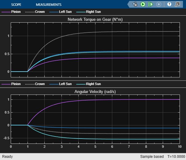
sim('CustomGearLibraryDifferentialGear');The simulation shows the key behavior of differentials. Both sun gears experience nearly the same torque, but because the left side has more resistance, the left sun gear rotates more slowly than the right sun. The torques are slightly different due to meshing losses.
Close the model.
close_system('CustomGearLibraryDifferentialGear/Scope', 0);