Simulation Parameters Used in Parallel Link Design
You can set parameters that control how a simulation is run in Parallel Link Designer using the Simulation Parameters dialog from the Setup > Simulation Parameters menu item. This dialog contains a table with parameters, their values, and the part of the analysis flow they affect. You can sort the columns by clicking on the table headers.
Non-STAT Mode SPICE Simulation
These parameters affect the SPICE simulation in non-STAT mode.
| Parameter | Description |
|---|---|
| Rise Time | Edge time of the stimulus input to the driver in the SPICE simulation. It can be overridden on a model-by-model basis. The default is 100 ps. |
| Tran Extension | Add time to the simulation. The default simulation time in the SPICE ".tran" statement is one bit time plus 4 ns past the last transition in the stimulus. This is to ensure that the receiver transition of the last stimulus transition will occur within the simulation time. For very long interconnects of approximately 24 inches or more, you may need to extend simulations further. The default is 0 ns. |
| Tran Time Step | Initial time step in the SPICE ".tran" statement and the plotting time step for pre-layout and post-layout transfer net simulations. The default is 20 ps. |
| Max Tran Time Step | Maximum time step to use during analysis. The default is 20 ps. |
| Stdload Tran Time Step | Initial time step in the SPICE ".tran" statement and the plotting time step for standard load simulations. The default is 20 ps. |
STAT Mode SPICE Simulation
These parameters affect the SPICE simulation in STAT Mode. STAT Mode is a simulation mode that uses a statistical engine to perform network characterization, statistical and time domain simulations. For more information, see Using STAT Mode.
| Parameter | Description |
|---|---|
| STAT Rise Time | Edge time of the stimulus input to the driver in the SPICE simulation. It can be overridden on a model-by-model basis. The default is 1 ps. |
| STAT Tran Time Step | Initial time step in the SPICE “.tran” statement and the plotting time step for pre-layout and post-layout transfer net simulations. The default is 2 ps. |
| STAT Max Tran Time Step | Maximum time step to use during analysis. The default is 1 ps. |
Waveform Analysis Parameters
These parameters affect waveform analysis.
| Parameter | Description |
|---|---|
| Skip Data Edge | Number of edges to skip at the beginning of waveforms of Type Data.
Skipped edges are not checked for overshoot or quality violations and are not used
for etch delay calculation. The default is |
| Skip Strobe Edge | Number of edges to skip at the beginning of waveforms of Type Strobe.
Skipped edges are not checked for overshoot or quality violations and are not used
for etch delay calculation. The default is |
| Skip Clock Edge | Number of edges to skip at the beginning of waveforms of Type Clock.
Skipped edges are not checked for overshoot or quality violations and are not used
for etch delay calculation. The default is |
| Skip Time | Amount of time to skip at the beginning of a waveform before starting waveform processing. No overshoot or waveform quality checks are done in the skipped time and any edges in skipped time are ignored for etch delay calculation. The default is 0 ns. In cases where a pulse width is reported (such as Derating Details), data will be reported for the edge before the first edge skipped. For example, if three edges are skipped there will be data for edge number three in some reports. |
STAT Mode Analysis Parameters
These parameters affect STAT mode analysis.
| Parameter | Description |
|---|---|
| Samples Per Bit | The number of time steps in a bit time. Defines the time step used in the STAT Mode “.tran” statement. |
| Max Channel Delay | User-supplied value for the maximum length of the channel impulse response. Goes into FFT block size calculation, which also defines the message length used for statistical analysis. |
| Target BER | An array of error rates at which eye height and width are to be measured. The array is sorted smallest to largest on focus change. If fewer than four values are entered the results will include four values, the additional values will be created by multiplying the last value by 1e3. |
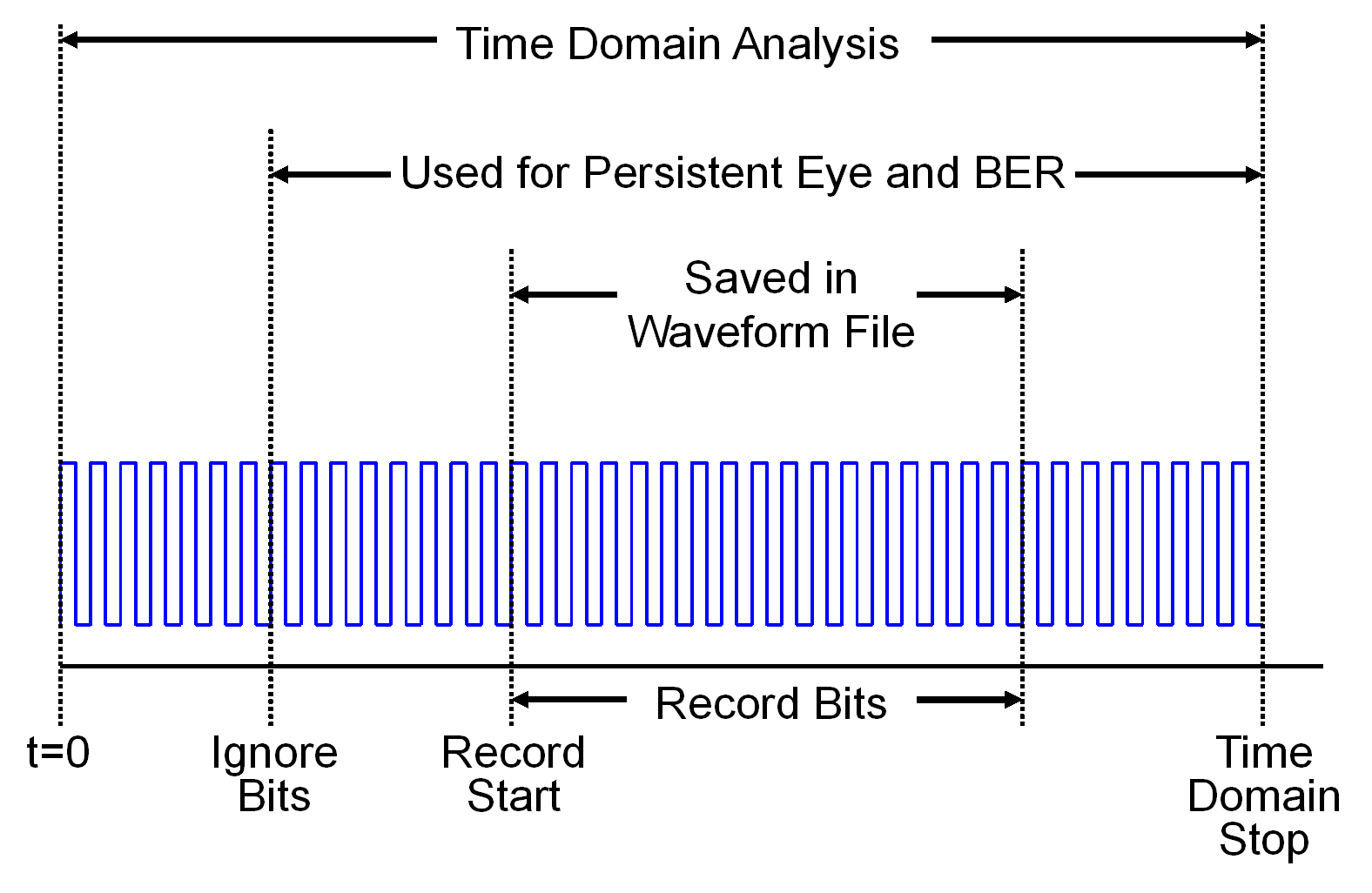
| Record Start | Time at which to start saving waveforms in a STAT Mode time domain simulation. |
| Record Bits | Number of bits of the waveform to save. |
| Waveform Analysis Bits | The number of bits from the STAT Mode simulation to use for Waveform Analysis. |
| Minimum Ignore Bits | STAT Mode time domain waveform analysis will start at this time in the simulation. Allows time for all of the AMI models to reach steady state. This is used if models do not define Ignore Time set in the AMI model, or the defined Ignore Time is less than this value. In other words, the larger of this value or a value from a model is used as the Ignore Bits for the analysis. |
| Time Domain Stop | The stop time of the STAT Mode time domain simulation. |
| Block Size | The number of samples in a single waveform segment in a time domain simulation. This sets the granularity of the parameter outputs returned by AMI models. Also used in determining FFT block size. |
| Output Clock Ticks | If yes, then QCD Time Domain Simulation will output the recovered clock ticks to a file. |
| STATify | Control how statistical techniques are applied to time domain simulations and Getwave-only models. The values are:
|
| Step Response Type | Step response used by STAT mode. The app supports rising, falling, and dual step responses. |
| SPICE Ignore Bits | The time before the start of the SPICE step in the STAT Mode step response simulation. It is either in UI or in units of seconds. |
| Include IBIS Package | Include (Yes) or do not include (No) IBIS Package. |
This figure demonstrates the relationship of several STAT Mode time domain simulation parameters.
Two of the STAT mode analysis parameters, Max Channel Delay and Block Size, determine the FFT block size used in network characterization and statistical analysis. The actual FFT block size is rounded up to the nearest power of two.
