Generate Entities Carrying Nested Data Structures
This example shows how to investigate the throughput of a vehicle service facility using the Simulink® Type Editor to create nested data structures carried by entities.
The facility has three service stations represented by three Entity Server blocks. The vehicles arriving at the facility are queued and then directed to one of the three service stations based on their size and mileage. It is assumed that the older vehicles require more service time.

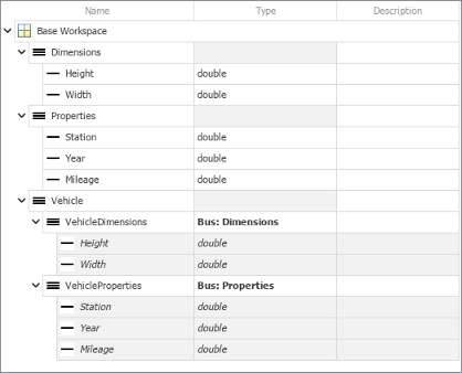
Create entities that represent vehicles arriving at a service facility. The entities carry data representing the vehicle dimensions and properties as nested bus objects. Vehicle dimensions include vehicle height and width in meters and vehicle properties include its age and current mileage.
On the Modeling tab, in the Design gallery, select Type Editor.
In the docked Type Editor, click
 to create a
 Simulink.Busobject.Set Name to
Dimensions.With the bus object selected, click
 twice to create two
Simulink.BusElementobjects. Name themHeightandWidth.Create another
Simulink.Busobject and set its Name property toProperties. Add threeSimulink.BusElementobjects namedStation,Year, andMileage.Create another
Simulink.Busobject and set its Name property toVehicle.Add two
Simulink.BusElementobjects and set their Name properties toVehicleDimensionsandVehicleProperties. For their Data type properties, use theBus: <object name>template, replacing<object name>withDimensionsandProperties, respectively.
Add an Entity Generator block. Double-click the Entity Generator block.
Select the Entity type tab. Set the Entity type to
Bus objectand Entity type name asVehicle.Vehicleis the bus object created by the Type Editor.Select the Event actions tab. In the Generate action field, enter:
% Vehicle Dimensions
entity.VehicleDimensions.Height = 1+rand();
entity.VehicleDimensions.Width = 1+rand();
% Vehicle Properties
entity.VehicleProperties.Year = randi([1996 2018]);
entity.VehicleProperties.Mileage = randi([50000 150000]);
The vehicles arrive at the facility with random dimensions and properties.
Add an Entity Queue block and rename it Vehicle Queue.
In the Main tab, set the Capacity to
Inf.Select the Event actions tab. In the Entry action field, enter this code to specify service station selection for vehicles.
% If the height and width of the vehicle are greater than 1.5 m, select Station 1.
if entity.VehicleDimensions.Width > 1.5 && entity.VehicleDimensions.Height > 1.5
    entity.VehicleProperties.Station = 1;
% Else, if the vehicle's mileage is greater than 90000 km, select Station 2.
else if entity.VehicleProperties.Mileage > 90000
     entity.VehicleProperties.Station = 2;
% If the vehicle's mileage is less than 90000 km, select Station 3.
else
     entity.VehicleProperties.Station = 3;
end
end
The vehicles are queued to be directed to the correct service station and vehicle dimensions and properties are used to select the appropriate service station.
Add an Entity Output Switch block.
Set the Number of output ports to
3.Set the Switching criterion to
From attribute.Set the Switch attribute name to
VehicleProperties.Station.
The Entity Output Switch block directs the vehicles to the stations based on the specified
Stationattribute.Add an Entity Server block that represents the service station. Rename the block Service Station 1.
In the Main tab, set the Service time source to
MATLAB action.In the Service time action field, enter:
if entity.VehicleProperties.Year > 2015
    dt = 1;
else
    dt = 5;
end
It is assumed that the vehicle service time is longer for older vehicles.
In the Statistics tab, select Number of entities departed, d statistic and connect it to a scope.
Connect Service Station 1 to an Entity Terminator block.
Follow the same steps to create Service Station 2 and Service Station 3 and connect them as shown.
Increase the simulation time to
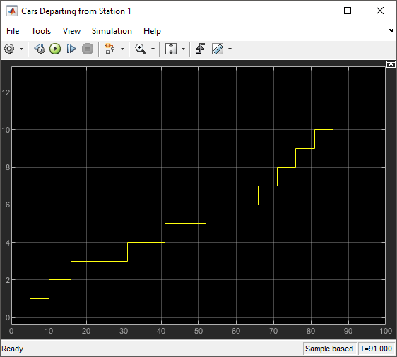
100and run the simulation.Observe the number of vehicles served at Service Station 1.
Observe the number of vehicles served at Service Station 2.

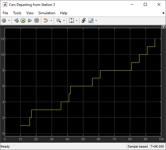
Observe the number of vehicles served at Service Station 3.
See Also
Entity Generator | Entity Server | Queue | Entity Output Switch