Type Editor
Create, modify, and manage types, such as bus objects
Renamed from Bus Editor in R2022b
Description
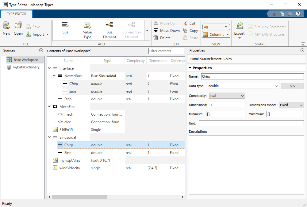
The Type Editor lets you interactively create, modify, and manage types.
Supported types include:
Simulink.Busobjects withSimulink.BusElementobjectsSimulink.ConnectionBusobjects withSimulink.ConnectionElementobjectsSimulink.ValueTypeobjectsSimulink.AliasTypeobjectsSimulink.NumericTypeobjectsSimulink.data.dictionary.EnumTypeDefinitionobjects in data dictionaries
The Type Editor has two variations:
The standalone Type Editor opens in a new window and supports the base workspace and data dictionaries. The Sources pane lets you quickly switch among the available sources.
The docked Type Editor (since R2023b) opens in the context of a model window and supports the external data sources used by the model. For example, if a model uses a data dictionary and the base workspace, the docked Type Editor display the types from these sources grouped by source. (since R2024a) For more information about data sources, see Determine Where to Store Variables and Objects for Simulink Models.
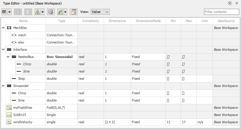
The Type Editor has an interactive table that provides information about the objects, such as hierarchy and properties.
To select which columns appear in the table, change the view. Alternatively, right-click a column title and select the desired columns. Supported views include:
Default(docked Type Editor only) — Data type and description columnsValue— Columns relevant to simulationCode(standalone Type Editor only) — Columns relevant to code generationAll— All columns
Use the table to:
Filter objects — Enter a universal filter or a column-specific filter.
Sort objects — Click individual column headers. (since R2026a)
Edit objects — Double-click a value in the table and enter a new value. When you enter a value that is not supported, a diagnostic message appears in this pane.
Batch edit objects — Select objects of the same type that you want to edit. Double-click a value of one of the selected objects and enter a new value. The new value applies to all selected objects.
Navigate among types — Right-click an object that references another object and select Go to. Alternatively, click an object to highlight its referenced object. Use this navigation to bring you to the editable instance of a bus object and its elements.
Reorder nested objects — Drag the nested objects to a new position.
Cut, copy, and paste objects — Right-click an object and select the desired action. Alternatively, in the standalone Type Editor, use the standard keyboard shortcuts for these actions.
Delete objects — Click
 . Alternatively, in the standalone
Type Editor, press Delete.
. Alternatively, in the standalone
Type Editor, press Delete.
Note
When you delete a bus object, you also delete the bus element objects it contains. Update any blocks that specify the deleted object. To find where a bus object is used in a model, see Finding Blocks That Use a Specific Variable.
Note
Changes that create, reorder, or delete objects take effect immediately in the base workspace. The interactive table does not support undo or redo actions.
To focus on one object at a time and edit the object properties, use the Property Inspector. When you select an object in the Type Editor, the Property Inspector shows the properties of that object. In the Property Inspector, when you enter a value that is not supported by a property, a diagnostic message appears. To undo or redo a change, right-click the corresponding box. Then, select Undo or Redo.
How you access the Property Inspector depends on the variation of the Type Editor that you have open.
Standalone Type Editor — Use the Properties pane.
Docked Type Editor — From the Simulink® Toolstrip, on the Simulation tab, in the Prepare gallery, select Property Inspector.
The Type Editor can export object definitions to a MAT file
(.mat) or function (.m).
To create a MATLAB® structure or Simulink.Parameter object from a
Simulink.Bus object, use the standalone Type
Editor.
Open the Type Editor
Open the standalone Type Editor.
In the docked Type Editor, click
 .
.Before R2026a: Click
 .
.In the MATLAB Command Window, enter
typeeditor.
Open the docked Type Editor.
In the Simulink Toolstrip, on the Modeling tab, in the Design section, click the down arrow on the far right. Then, under Design, click Type Editor.
In the Simulink Editor, press Ctrl+Shift+P.
Examples
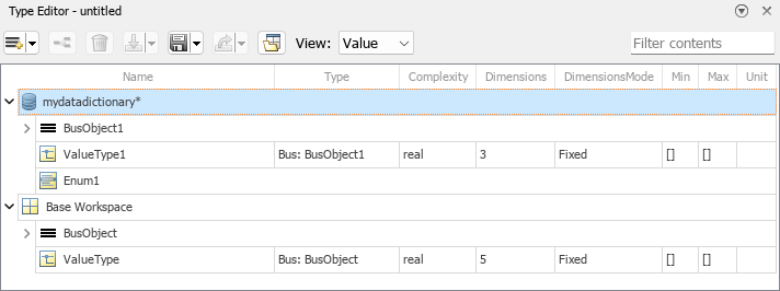
You can create and edit types in multiple external data sources with the Type Editor.
In the standalone Type Editor, use the Sources pane to switch among external data sources, such as the base workspace and a data dictionary.
To open a data dictionary in the standalone Type Editor:
In the Type Editor toolstrip, click Open for an existing dictionary or New for a new dictionary.
In the dialog box that opens, specify the data dictionary that you want to use.
Click Open or Save, depending on whether you are opening an existing or new dictionary.
To add external data sources for your model via the docked Type Editor:
Click
 .
.Before R2026a: Click
 .
.In the Model Properties dialog box, configure the external data sources for your model. For example, add a data dictionary and toggle whether your model has access to the base workspace. For more information, see Migrate Models to Use Simulink Data Dictionary.
To replace or remove external data sources for your model via the docked Type Editor:
Click the down arrow button
 . Then, select
Link.
. Then, select
Link.In the Model Properties dialog box, configure the external data sources for your model. For example, replace or remove a data dictionary and toggle whether your model has access to the base workspace. For more information, see Migrate Models to Use Simulink Data Dictionary.
In the Type Editor, before you create types, select the external data source that you want to contain the new types.
How you create types in the Type Editor depends on whether you open the Type Editor in the context of a model window or as a standalone window.
In the standalone Type Editor:
Select the external data source that you want to contain the new types.
Click the down arrow on the far right of the Add section to expand the gallery.
Select the type you want to create.
Bus — Create a
Simulink.Busobject.Connection Bus — Create a
Simulink.ConnectionBusobject.Alias Type — Create a
Simulink.AliasTypeobject.Value Type — Create a
Simulink.ValueTypeobject.Numeric Type — Create a
Simulink.NumericTypeobject.Enum Type (data dictionary only) — Create a
Simulink.data.dictionary.EnumTypeDefinitionobject.
Tip
Toggle the
 button to promote your
most commonly used types to the top of the gallery.
button to promote your
most commonly used types to the top of the gallery.To add elements to bus objects, select the bus object. Then, in the gallery, click the appropriate button once for each element you want to add.
Bus Element — Create a
Simulink.BusElementobject in aSimulink.Busobject.Connection Element — Create a
Simulink.ConnectionElementobject in aSimulink.ConnectionBusobject.
The new type appears in the interactive table.
In the docked Type Editor:
Select the external data source that you want to contain the new types.
Click the down arrow button
 .
.Select the type you want to create.
Bus object — Create a
Simulink.Busobject.Connection bus object — Create a
Simulink.ConnectionBusobject.Alias type — Create a
Simulink.AliasTypeobject.Value type — Create a
Simulink.ValueTypeobject.Numeric type — Create a
Simulink.NumericTypeobject.Enumerated type (data dictionary only) — Create a
Simulink.data.dictionary.EnumTypeDefinitionobject.
To add elements to bus objects, select the object. Then, click
 once for each element you
want to add.
once for each element you
want to add.
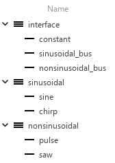
An element in a bus can be another bus, which can in turn contain subordinate buses, to any depth. To define a multilevel bus hierarchy by using bus objects, you can nest bus objects in each other.
Suppose you want to define a bus hierarchy that contains two buses and a
constant signal. The nested buses are already defined by bus objects named
sinusoidal and nonsinusoidal. For
the top level of the bus hierarchy, you create a bus object named
interface. This bus object has three elements:
constantfor the constant signalsinusoidal_busfor the bus defined by thesinusoidalbus objectnonsinusoidal_busfor the bus defined by thenonsinusoidalbus object
To nest the bus objects named sinusoidal and
nonsinusoidal in the bus object named
interface:
For the element named
sinusoidal_bus, set the Type column tosinusoidalorBus: sinusoidal.For the element named
nonsinusoidal_bus, set the Type column tononsinusoidalorBus: nonsinusoidal.
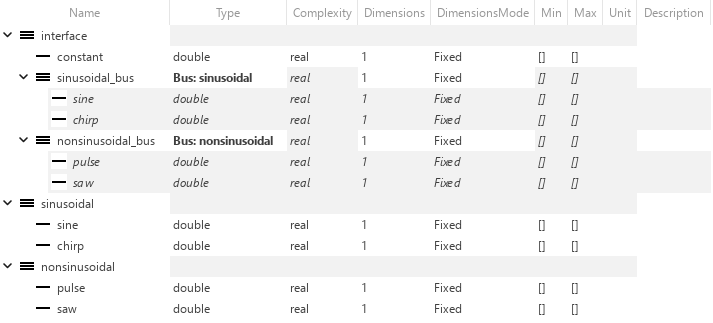
When you set the data type of a Simulink.BusElement
object to a Simulink.Bus object, the
Bus: prefix is optional.
You can import types from a function, script, or MAT file into the Type Editor.
How you import types in the Type Editor depends on whether you open the Type Editor in the context of a model window or as a standalone window.
Standalone Type Editor — In the Type Editor toolstrip, click the Import down arrow button.
Docked Type Editor — Click the down arrow button
 .
.
Select one of the options.
MAT File — Import types from a MAT file (
.mat).Function or Script — Import types from a MATLAB function or script (
.m).
In the Import into Base Workspace dialog box, select the file that defines the types.
Click Open.
The import loads the complete contents of the file, not just the types. The table displays the available types.
Use filters to quickly find objects by name or property value.
The filter can be a search term or regular expression. For information about regular expressions, see Regular Expressions.
For example, to quickly find objects with a double data
type, type double in either:
The Filter contents box at the top right of the interactive table
The box that appears when you pause on the Type column title, then click the button that appears
As you type, the table updates dynamically to show only the objects whose names or property values match the filter and their parents. The comparison is not case-sensitive.
You can use the Type Editor to modify types in external data sources, such as the base workspace and data dictionaries.
To edit one or more types in the Type Editor, use the interactive table.
Select the types that you want to update.
To select multiple noncontiguous types, hold Ctrl and select each element.
To select multiple contiguous types, hold Shift and select the first and last element.
To select all types, first select one type. Then, press Ctrl+A.
Double-click the property value that you want to change for all the selected types. Then, enter the new value.
When you commit the new value, the change applies to all the selected types that are of the same base type as the type you changed, for example, all the
Simulink.Busobjects or all theSimulink.ValueTypeobjects.
You can edit contents in the filtered view just like the unfiltered view. Elements that no longer match the filter disappear from the table. Conversely, if some activity outside the Type Editor changes a filtered type so that the type passes the current filter, the type immediately becomes visible.
Operations affect only the available types. A type that a filter hides is unaffected by the operation. To act on all available types, clear the filter.
To edit one type at a time, use the Property Inspector. Some properties are available only in the Property Inspector.
For bus types:
Edit the properties of a bus object and its elements at the top level, not where the bus object is specified as a data type. To go to the editable instance of the object, right-click the dimmed object and select Go to.
To reorder bus element objects, select and drag the elements to a new position.
While the Type Editor displays service interfaces, you must use the Architectural Data Editor or Interface Editor (System Composer) to edit their properties. (since R2023b)
When you create or modify types, save the types for future use. If blocks specify these types, the types are required for simulation.
The Type Editor can save types to a MAT file
(.mat), MATLAB function (.m), or data dictionary
(.sldd).
To save all the types that are in the base workspace:
How you save types in the Type Editor depends on whether you open the Type Editor in the context of a model window or as a standalone window.
Standalone Type Editor — In the Type Editor toolstrip, click the Export down arrow button.
Docked Type Editor — Click the down arrow button
 .
.
Select one of the options.
MAT File — Export types to a MAT file (
.mat).Function (Cell Format) — Export types to a MATLAB function that uses the more compact cell format.
Function (Object Format) — Export types to a MATLAB function that uses the more readable object format.
In the Export dialog box, specify the file name. Then, click Save.
To save a subset of the types that are in the base workspace:
Select the types to save.
Right-click one of the selected types. Then, click one of these options.
Export to File — Export the selected types to a file.
Export with Dependencies to File — Export the selected types and any types they reference to a file.
Select one of the file options.
MAT File — Export types to a MAT file (
.mat).Function (Cell Format) — Export types to a MATLAB function that uses the more compact cell format.
Function (Object Format) — Export types to a MATLAB function that uses the more readable object format.
In the Export dialog box, specify the file name. Then, click Save.
Alternatively, cut or copy the objects from the base workspace. Then, paste them in a data dictionary.
To save the objects in a data dictionary, your action depends on the variation of the Type Editor that you have open.
Standalone Type Editor — In the Sources pane, select the modified dictionary. Then, in the Type Editor toolstrip, click Save.
Docked Type Editor — Select the modified dictionary. Then, click
 .
.
Since R2023b
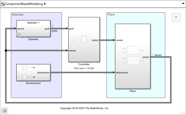
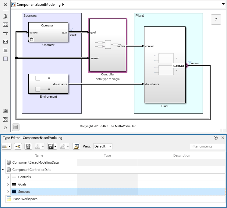
When you open the Type Editor in the context of a model, the Type Editor displays the types used by a model. The Type Editor helps you find where these types are used in the model by highlighting the corresponding blocks and ports for a selected type.
Open the ComponentBasedModeling project. Optionally, compile the model that opens. To compile the model, on the Modeling tab of the Simulink Toolstrip, click Update Model or Run. Compiling the model updates the line styles, which you can use to visually identify buses.
To view the types that the model uses, on the Modeling tab, in the Design gallery, click Type Editor. Alternatively, press Ctrl+Shift+P.
To expand an external data source, click the arrow next to the data source name.
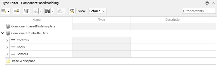
The top model in the model hierarchy has access to three external data sources:
ComponentBasedModelingData— The data dictionary associated with the top model in the model hierarchyComponentControllerData— A referenced data dictionary that contains the types used at the controller interfaceBase Workspace— The base workspace
The controller interface uses Simulink.Bus objects named Controls, Goals, and Sensors.
To display where the model uses a bus object, click the bus object in the Type Editor. For example, click Sensors.

The block diagram highlights the Subsystem block named Controller because the subsystem uses the Sensors bus object.
Double-click the Controller subsystem to open it.
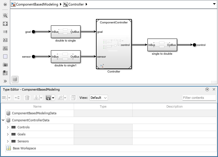
A subsystem has access to the same external data sources as its parent model.
In the Type Editor, click Sensors.

The block diagram highlights two ports because they use the Sensors bus object.
The OutBus port of the Subsystem block named
double to single1The sensor port of the Model block named
Controller
Double-click the Controller model to open it.
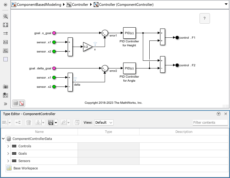
The referenced model named ComponentController has access to two external data sources:
ComponentControllerData— A data dictionary that contains the types used at the controller interfaceBase Workspace— The base workspace
The ComponentBasedModelingData dictionary no longer appears in the Type Editor.
In the Type Editor, click Sensors.

The block diagram does not highlight blocks or ports because the top-level bus object does not correspond with a visible block or port in the block diagram.
In the Type Editor, expand Sensors. Then, click one of its elements. For example, click the element named x1.

The block diagram highlights the In Bus Element blocks that select the element named x1 from the Sensors bus object.
Since R2023b
When you open the Type Editor in the context of a model, you can use the Type Editor to assign the selected type to a block.
Open the ComponentBasedModeling project. Optionally, compile the model that opens. To compile the model, on the Modeling tab of the Simulink Toolstrip, click Update Model or Run. Compiling the model updates the line styles, which you can use to visually identify buses.

To open the Type Editor, on the Modeling tab, in the Design gallery, click Type Editor. Alternatively, press Ctrl+Shift+P. To expand an external data source, click the arrow next to the data source name.

Suppose you want to define the interface that provides the sensor data in the top model. You can use the Simulink.Bus object named Sensors to define this interface.
In the Type Editor, click Sensors.

The sensor port of the Subsystem block named Plant provides the sensor data, but the port is not highlighted because it does not use the Sensors bus object.
On the Subsystem block named Plant, select the sensor port.
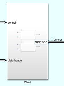
In the Type Editor, right-click Sensors. Then, select Assign type to selected blocks and ports.
The sensor port is now highlighted because it uses the Sensors bus object.
Double-click the Subsystem block named Plant.
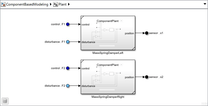
Two Out Bus Element blocks correspond with the sensor port.
Double-click either of these Out Bus Element blocks.

The Out Bus Element blocks that create the sensor interface are now defined by the Sensors bus object.
You can use the Type Editor to create MATLAB structures for initialization.
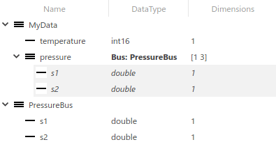
Suppose you have a Simulink.Bus object named
MyData that contains two elements named
temperature and pressure.
temperature— Signal with a data type ofint16pressure— Nested array of buses with a data type ofBus: PressureBusand dimensions specified as[1 3]
The nested Simulink.Bus object named PressureBus has
two elements named s1 and s2.
Right-click the Simulink.Bus object named
MyData. Then, select Create MATLAB
Structure. Alternatively, in the standalone Type
Editor, select the Simulink.Bus object. Then, in
the Type Editor toolstrip, click MATLAB
Structure.
Specify a name and location for the new MATLAB structure.
The MATLAB structure specifies an initial condition of
0 for each element.
MyData_MATLABStruct = struct;
MyData_MATLABStruct.temperature = int16(0);
MyData_MATLABStruct.pressure = struct;
MyData_MATLABStruct.pressure(1).s1 = 0;
MyData_MATLABStruct.pressure(1).s2 = 0;
MyData_MATLABStruct.pressure(2).s1 = 0;
MyData_MATLABStruct.pressure(2).s2 = 0;
MyData_MATLABStruct.pressure(3).s1 = 0;
MyData_MATLABStruct.pressure(3).s2 = 0;
Optionally, change the initial conditions of the structure elements.
Use the MATLAB structure to specify the Initial condition parameter of a block such as a Unit Delay block.
To create a MATLAB structure for a top-level Simulink.Bus object
that defines an array of buses, use the Simulink.Bus.createMATLABStruct function.
Tips
A bus object cannot directly or indirectly reference itself. If you define a circular structure, the Type Editor keeps the original data type of the element that would have completed the circle.
To create
Simulink.BusandSimulink.BusElementobjects from a bus in your model, such as the output bus of a Bus Creator block or bus element port, use theSimulink.Bus.createObjectfunction.
Version History
Introduced before R2006aTo aid the transition between the docked Type Editor and Interface Editor as you navigate between Simulink models and architecture models, the Type Editor supports new functionality and has updated button icons.
When you create a type, you can enter a new name right away. In previous releases, you must double-click the default name to enter a new name.
To sort types, you can now click individual column headers. In previous releases, the Type Editor does not support sorting.
When you specify a bus object in the Type column, the Type Editor displays the bus hierarchy regardless of whether you include the
Bus:prefix. In previous releases, the bus hierarchy displays only when you include theBus:prefix.When you rename a bus object, the Type Editor updates any references to the bus object in other bus objects. The Type Editor does not update references to the bus object in value types.
The Link external sources button has a new icon
 . The former Link external sources icon is
now used by the Open standalone Type Editor button
. The former Link external sources icon is
now used by the Open standalone Type Editor button
 . This change aligns the button icons used
by the Type Editor and the Interface Editor for
similar actions. In previous releases, the Open standalone Type Editor
button has a different icon
. This change aligns the button icons used
by the Type Editor and the Interface Editor for
similar actions. In previous releases, the Open standalone Type Editor
button has a different icon  .
.
For more information, see Interface Editor (System Composer).
When the Type Editor is docked in a model window, the Type Editor displays the available types for the model grouped by source.
To add or remove external data sources, click ![]() . Alternatively, click the
. Alternatively, click the ![]() button arrow. Then, select
Link.
button arrow. Then, select
Link.
When you open the Type Editor from a model, the Type Editor is docked as a pane in the model window.
This integration lets you view where a type is used in your model. For example, you can click a type in the docked Type Editor to highlight the blocks that use the type. For more information, see View Types in Models Using Docked Type Editor.
To open the Type Editor in a standalone window, click ![]() .
.