Continuous Wave
Model constant envelope source
Libraries:
RF Blockset /
Circuit Envelope /
Sources
Description
The Continuous Wave block models a constant modulation on a carrier in the RF Blockset™ circuit envelope simulation environment. For an introduction to RF simulation, see the example, Simulate High Frequency Components.
The block implements the relation
or
at the carrier ωk, depending on the source type.
Continuous Wave block mask icons are dynamic and show the current state of the applied noise parameter. For more information, see Continuous Wave Block Icons.
Examples
Carrier to Interference Performance of Weaver Receiver
A classic superheterodyne architecture filters images prior to frequency conversion. In contrast, image-reject receivers remove the images at the output without filtering but are sensitive to phase offsets.
Model LO Phase Noise
Model and visualize LO phase noise. A mixer transfers local oscillator (LO) phase noise directly to its output.
Parameters
Ideal Voltage
— The block simulates a constant voltage envelope v0 at the specified Carrier frequencies. The envelope has real and imaginary parts specified by the Constant in-phase value and Constant quadrature value parameters.Ideal Current
— The block simulates a constant current envelope i0 at the specified Carrier frequencies. The envelope has real and imaginary parts determined by the Constant in-phase value and Constant quadrature value parameters.Power
— The block simulates the constant voltage envelopewhere:
P0 is the value of the Available power parameter
Zs is the value of the Source impedance (ohms) parameter.
ϕ is the value of the Angle (degrees) parameter.
In-phase modulations for each of the Carrier frequencies, specified as a vector of real numbers. Specify the units from the corresponding drop-down list.
Dependencies
To enable this parameter, on the Source type tab,
choose Ideal voltage
or Ideal
current
.
Quadrature modulations for each of the RF circuit carrier frequencies, specified as a vector of real numbers. Specify the units from the corresponding drop-down list.
Dependencies
To enable this parameter, on the Source type tab,
choose Ideal voltage
or Ideal
current
.
Input impedance of source, specified as a positive real number or a
complex number. The complex number must contain real and imaginary parts
greater than or equal to 1e-18
ohms.
Dependencies
To enable this parameter, on the Source type tab,
choose Power
.
Available power at the specified Carrier frequencies,
specified as a vector of real numbers. Specify the units from the drop-down
list. The default value is
0
W
.
Dependencies
To enable this parameter, on the Source type tab,
choose Power
. The default value is
0
W
Phase angle of power waves at the specified Carrier
frequencies, specified as a vector of real numbers. The
default value is 0
degrees.
Dependencies
To enable this parameter, on the Source type tab,
choose Power
.
Carrier frequencies, specified as a vector of real positive numbers. The
elements in the carrier frequencies are combinations of fundamental tones
and corresponding harmonics in the Configuration block. The default
value is 0
Hz
.
Select this parameter, to add phase noise to your system with continuous wave source.
Phase noise frequency offset, specified as a scalar or vector or matrix with each element units in hertz.
If you specify a matrix, each column should correspond to a non-DC carrier frequency of the CW source. The frequency offset values must be bounded by the envelope bandwidth of the simulation. For more information see, Configuration.
Dependencies
To enable this parameter, select Add phase noise.
Phase noise level, specified as a scalar or vector or matrix with element unit in decibel per hertz.
If you specify a matrix, each column should correspond to a non-DC carrier frequency of the CW source. The frequency offset values must be bounded by the envelope bandwidth of the simulation. For more information see, Configuration.
Dependencies
To enable this parameter, select Add phase noise.
Select this parameter to automatically calculate impulse response for phase noise. Clear this parameter to manually specify the impulse response duration using Impulse response duration.
Dependencies
To enable this parameter, select Add phase noise.
Impulse response duration used to simulate phase noise, specified as a scalar in seconds. You cannot specify impulse response if the amplifier is nonlinear.
Note
The phase noise profile resolution in frequency is limited by the duration of the impulse response used to simulate it. Increase this duration to improve the accuracy of the phase noise profile. A warning message appears if the phase noise frequency offset resolution is too high for a given impulse response duration, specifying the minimum duration suitable for the required resolution
Dependencies
To set this parameter, first clear Automatically estimate impulse response duration.
The block plots the phase noise characteristics based on the parameters specified in the Impairments tab and either the Envelope bandwidth parameter in the Configuration block when available or the value specified in the Phase noise frequency offset (Hz) parameter.
Dependencies
To enable this parameter, select Add phase noise.
Select this option to internally ground and hide the negative terminals. To expose the negative terminals, clear the option. By exposing these terminals, you can connect them to other parts of your model.
Algorithms
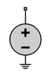
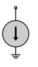
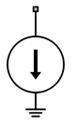
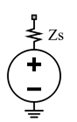
This table shows you how the icons on this block vary based on the state of the Simulate noise and Source type parameters on the block.
Source type | Simulate noise: on | Simulate noise: off |
---|---|---|
Ideal voltage |
|
|
Ideal current |
|
|
Power |
|
|
Version History
Introduced in R2010bThe Continuous Wave block estimates the impulse response duration using the Phase noise frequency offset (Hz) parameter and visualizes the phase noise characteristics when you click the Plot phase noise characteristics button.
Starting in R2021b, the Continuous Wave block icon is now updated. The block icons are now dynamic and show the current state of the noise parameter.
When you open a model created before R2021b containing a Continuous Wave block, the software replaces the block icon with the R2021b version.
MATLAB Command
You clicked a link that corresponds to this MATLAB command:
Run the command by entering it in the MATLAB Command Window. Web browsers do not support MATLAB commands.
Sélectionner un site web
Choisissez un site web pour accéder au contenu traduit dans votre langue (lorsqu'il est disponible) et voir les événements et les offres locales. D’après votre position, nous vous recommandons de sélectionner la région suivante : .
Vous pouvez également sélectionner un site web dans la liste suivante :
Comment optimiser les performances du site
Pour optimiser les performances du site, sélectionnez la région Chine (en chinois ou en anglais). Les sites de MathWorks pour les autres pays ne sont pas optimisés pour les visites provenant de votre région.
Amériques
- América Latina (Español)
- Canada (English)
- United States (English)
Europe
- Belgium (English)
- Denmark (English)
- Deutschland (Deutsch)
- España (Español)
- Finland (English)
- France (Français)
- Ireland (English)
- Italia (Italiano)
- Luxembourg (English)
- Netherlands (English)
- Norway (English)
- Österreich (Deutsch)
- Portugal (English)
- Sweden (English)
- Switzerland
- United Kingdom (English)