Systèmes gazeux
Explorez des exemples qui illustrent la modélisation, le contrôle et la simulation de systèmes gazeux.
Sélection d՚exemples

Circuit de commande pneumatique
Cet exemple montre comment utiliser les composants gazeux de la Foundation Library pour modéliser un actionneur pneumatique contrôlé. Le sous-système masqué Directional Valve a été créé avec des blocs Variable Local Restriction (G) pour modéliser l’ouverture et la fermeture des trajectoires d’écoulement. Le sous-système masqué Double-Acting Actuator a été créé avec des blocs Translational Mechanical Converter (G) pour modéliser l’interface entre le réseau gazeux et le réseau mécanique de translation.

Pneumatic Motor Circuit
How a pneumatic vane motor can be modeled using the Simscape™ language. The Pneumatic Motor component is built using the Simscape Foundation gas domain. It inherits from the foundation.gas.two_port_steady base class, which contains common equations that implement the upwind energy flow rate and the gas properties at the ports. The Pneumatic Motor subclass implements equations that describe behaviors specific to the component, such as the motor torque and flow rate characteristics and the mass and energy balance. The Pneumatic Motor block is inserted into the model using the Simscape Component block without the need to generate a separate library.
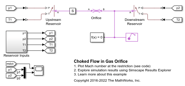
Débit restreint dans un orifice à gaz
Cet exemple illustre le comportement de restriction d'un orifice de gaz modélisé par le bloc Local Restriction (G). Les blocs Controlled Reservoir (G) permettent d’établir des conditions limites de pression et de température contrôlées à partir du sous-système Reservoir Inputs afin de tester l'orifice de gaz.

Cycle de Brayton (turbine à gaz) avec des composants personnels
Cet exemple modélise un groupe auxiliaire de puissance de turbine à gaz basé sur le cycle de Brayton. Les blocs Compressor et Turbine sont des composants personnalisés gazeux de la Foundation Gaz Library Simscape™. La puissance acheminée jusqu’au système est représentée par l'injection de chaleur dans la chambre de combustion. La chimie de la combustion proprement dite n'est pas modélisée. Un seul arbre relie le compresseur à la turbine, de sorte que la puissance émanant de la turbine entraîne le compresseur. Le groupe auxiliaire de puissance est une turbine qui détend encore le flux d'échappement afin de produire une puissance de sortie.

Ventilation de bâtiments
Cet exemple présente un modèle du circuit de ventilation d’un bâtiment. Le volume d’air à l’intérieur du bâtiment est divisé en quatre zones. Le système de ventilation insuffle de l’air frais dans la zone 1 et extrait l’air de la zone 3. L’air extrait peut éventuellement être recyclé et réintroduit dans la zone 1. Dans la zone 4, il est possible d’ouvrir une porte pour évacuer l’air dans l’atmosphère.

Gamma Stirling Engine
Model a Gamma Stirling engine using gas, thermal, and mechanical Simscape™ components and domains.
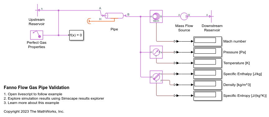
Fanno Flow Gas Pipe Validation
The Fanno flow model is an analytical solution of an adiabatic (perfectly insulated) compressible perfect gas flow through a constant area pipe with friction. This example shows a comparison and validation of the Simscape™ Pipe (G) block against the Fanno flow model. While you typically need empirical data to validate a block over a range of scenarios, it may still be useful to perform limited validation against analytical models for specific scenarios. This is because the theory and derivation behind the analytical model may provide more insight into where the block works well and how to address limitations. The comparison shows that, for short to moderate pipe lengths, the Simscape pipe model agrees well with the Fanno flow model. For long pipe lengths, a segmented pipe model agrees well with the Fanno flow model.

Compressor Map with Scattered Lookup
Gas flow through a compressor which is modeled using a simple controlled mass flow rate source. The compressor map that governs this mass flow rate is modeled using the PS Scattered Lookup (2D) block whose data coordinates are the pressure ratio (Pa/Pa) and the engine RPM, and the output is the mass flow rate (kg/s). The scattered lookup block performs delaunay triangulation on the input data (which is shown in plots below), and uses this to interpolate and calculate the mass flow rate based on the input. Scattered lookup allows modeling of the compressor even if the data provided is in an unstructured format.